
User Guide


Documentation Number 3PCIO1-0903 Manual Chapter 7 49
B&B Electronics Mfg Co – 707 Dayton Rd - PO Box 1040 - Ottawa IL 61350 - Ph 815-433-5100 - Fax 815-433-5104
B&B Electronics Ltd – Westlink Comm. Pk. – Oranmore, Galway, Ireland – Ph 353-91-792444 – Fax 353-91-792445
4. Check your Card Jumpers, and Driver Settings. See Chapter 2.
5. Make sure you have DTR Operation set to the correct mode.
Normal for RS-232, RS-485 Mode for RS-485. RS-422 mode
works in either setting provided that the mode jumpers are set
correctly.
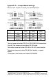
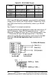
6. A loopback connection for RS-232 connects the Transmit
output to the Receive input (pins #2 & #3 on the DB9
connector). Use connections below to check all.
Fig. 7.1 RS-232 Loopback w/Handshaking Connections
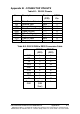
7. For RS-422 or 4-wire RS-485, connect the TD(A) to RD(A) and
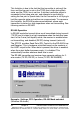
the TD(B) to RD(B). Then use the COMTest program to send
characters, and observe the characters being received.
Fig. 7.2 RS-422 or 4-wire RS485 Loopback Connections