
User Guide


B-2 Appendix B Documentation Number 3PCIO1-0903 Manual
B&B Electronics Mfg Co – 707 Dayton Rd - PO Box 1040 - Ottawa IL 61350 - Ph 815-433-5100 - Fax 815-433-5104
B&B Electronics Ltd – Westlink Comm. Pk. – Oranmore, Galway, Ireland – Ph +353 91-792444 – Fax +353 91-792445
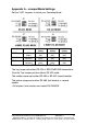
With 2-wire RS-485 mode operation, your connection cable must
jumper TD(A) to RD(A) and TD(B) to RD(B). Connect from TD(A)
and TD(B) to the Data A(−
−−
−) and Data B(+) wires of your RS-485
network.
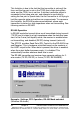
See Chapter 2 for example connections.
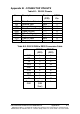
Note that the EIA RS-422 Specification labels data lines with an "A"
and "B" designator. Some RS-422 equipment uses a "−" and "+"
designator. In almost all cases, the "A" line is the equivalent of the
"−" line and the "B" line is the equivalent of the "+" line.
More
information on RS-422 communications can be found in the B&B
Electronics RS-422/485 Application Note (available on our
website)
.
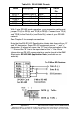
Table B.3: RS-422/485 Pinouts
Name Description Direction DB9M
Pin
RD(A) −
−−
−
Receive Data A Input 1
TD(B) + Transmit Data B Output 2
TD(A) −
−−
−
Transmit Data A Output 3
GND Signal Ground ------ 5
RD(B) + Receive Data B Input 9