
user manual


485SDA103798 Manual 23
B&B Electronics -- 707 Dayton Rd. -- PO Box 1040 -- Ottawa, IL 61350
PH (815) 433-5100 -- FAX (815) 434-7094
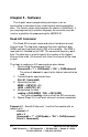
‘Get the value of channel 1
MSB$ = INPUT$ (1, #1)
LSB$ = INPUT$ (1, #1)
reading1 = (ASC(MSB$) * 256) + ASC(LSB$)
‘Get the value of channel 0
MSB$ = INPUT$ (1, #1)
LSB$ = INPUT$ (1, #1)
reading0 = (ASC(MSB$) * 256) + ASC(LSB$)
The value of reading1 is the result of the A/D conversion on
channel 1. The value of reading0 is the result of the A/D conversion
on channel 0.
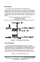
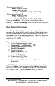
Read Digital I/O Command
The Read Digital I/O command returns a byte which
represents the states of the 3 digital input and 3 digital output states.
Bits 3-5 correspond to the states of digital inputs 0-2, and bits 0-2
correspond to the states of digital outputs 0-2. If a bit is a 0 then the
digital state of that digital I/O is LOW. If a bit is a 1 then the digital
state of the I/O is HIGH.
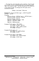
The steps to reading a digital I/O command are given below:
1. Constructing the command string:
Command$ = “!” + CHR$(addr) + “RD”
2. Transmitting the command string:
Print #1, Command$;
3. Receiving the data:
Reply$ = INPUT$ (1, #1)
4. Manipulating the data:
states = ASC(Reply$)
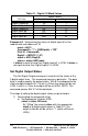
5. Determining an I/O’s status
status = states AND mask
6. Repeat Step 5 until the status of each I/O has been
determined.
By “ANDing” the value of states with the appropriate mask of an
I/O line, the status of can be determined. If status is equal to zero
then the I/O line is LOW. If status is not equal to zero then the I/O
line is HIGH. Table 5.1 shows the mask values for each I/O.