TPC-1261H GX3 LX800 Touch Panel Computer with 12.
Copyright The documentation and the software included with this product are copyrighted 2004 by Advantech Co., Ltd. All rights are reserved. Advantech Co., Ltd. reserves the right to make improvements in the products described in this manual at any time without notice. No part of this manual may be reproduced, copied, translated or transmitted in any form or by any means without the prior written permission of Advantech Co., Ltd. Information provided in this manual is intended to be accurate and reliable.
Product Warranty (1 year) Advantech warrants to you, the original purchaser, that each of its products will be free from defects in materials and workmanship for one year from the date of purchase. This warranty does not apply to any products which have been repaired or altered by persons other than repair personnel authorized by Advantech, or which have been subject to misuse, abuse, accident or improper installation.
CE This product has passed the CE test for environmental specifications when shielded cables are used for external wiring. We recommend the use of shielded cables. This kind of cable is available from Advantech. Please contact your local supplier for ordering information. FCC Class A This equipment has been tested and found to comply with the limits for a Class A digital device, pursuant to Part 15 of the FCC Rules.
Packing List Before setting up the system, check that the items listed below are included and in good condition. If any item does not accord with the table, please contact your dealer immediately. • 1 x TPC-1261H-A1 • 8 x Panel mounting clampers • 8 x Panel mounting screws • 1 x 3-Pin power connector • 1 x TPC x86 Series support CD • 1 x CompactFlash to IDE adapter board Safety Instructions 1. Read these safety instructions carefully. 2. Keep this User's Manual for later reference. 3.
13. Never open the equipment. For safety reasons, the equipment should be opened only by qualified service personnel. 14. If one of the following situations arises, get the equipment checked by service personnel: a. The power cord or plug is damaged. b. Liquid has penetrated into the equipment. c. The equipment has been exposed to moisture. d. The equipment does not work well, or you cannot get it to work according to the user's manual. e. The equipment has been dropped and damaged. f.
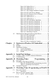
Contents Chapter Chapter 1 General Information ....................................... 2 1.1 1.2 Introduction ....................................................................... 2 Specifications .................................................................... 3 1.3 1.4 1.5 1.6 LCD Specifications ........................................................... 4 Touchscreen Specifications............................................... 4 Power...........................................................
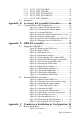
Figure 4.14:Update Driver - 1 ...................................... 25 Figure 4.15:Update Driver - 2 ...................................... 25 Figure 4.16:Update Driver - 3 ...................................... 26 Figure 4.17:Slave Bridge Installation Complete .......... 26 Figure 4.18:PCI-1602 Device Manager ....................... 27 Figure 4.19:PCI Serial port Device Manager .............. 28 Figure 4.20:Update Driver - 1 ...................................... 28 Figure 4.21:Update Driver - 2 .........
C.2.2 C.2.3 C.2.4 C.2.5 C.2.6 C.3 IOCTL _WDT_DISABLE: .......................................... 60 IOCTL_WDT_STROBE: ............................................ 60 IOCTL_WDT_GETTIMEOUT: .................................. 61 IOCTL_WDT_SETTIMEOUT: .................................. 61 IOCTL_WDT_REBOOT: ........................................... 61 Examples ......................................................................... 62 Appendix D Accessory Kit Assembly Procedure ............. 66 D.
Figure F.2:Install Wizard - 1 ....................................... 84 Figure F.3:Install Wizard - 2 ........................................ 85 Figure F.4:Install Wizard - 3 ........................................ 85 F.2 Uninstall the Driver......................................................... 86 F.3 Touchscreen Calibration ................................................. 87 Figure F.5:Uninstall -1 ................................................. 86 Figure F.6:Uninstall -2 ...................
CHAPTER 1 2 General Information This chapter gives background information on TPC-1261H..
Chapter 1 General Information 1.1 Introduction The TPC-1261H touch panel computer is a state-of-the-art HMI (Human Machine Interface). This operator interface with a 12.1” display is an x86-based platform with these key features: • Fanless By using a low-power processor, the system does not have to rely on fans, which often are unreliable and causes dust to circulate inside the equipment. • Bright Display The TFT LCD display suits industrial demands for clear interfaces.
1.2 Specifications 1.2.1 System Kernel • CPU: GeodeLink Control Processor LX800 500MHz • BIOS: Award 512KB flash memory • South Bridge: GeodeLink Control Processor CS5535 • VGA: GeodeLink Control Processor LX800 500MHz • Ethernet: Realtek RTL8100BL; IEEE 802.3u protocol compatible • Watchdog Timer: W83627 watchdog timer; 1.6 second timeout period • IDE: 1 EIDE channel supports one CompactFlash socket onboard (Master) and one IDE interface harddrive (Slave) 1.2.
Environment • Operating Temperature: 0 ~ 50° C (32 ~ 122° F) • Storage Temperature: -20 ~ 60° C (-4 ~ 140° F) • Humidity: 40° C @ 10~95% relative humidity (non-condensing) • Vibration: 1 grms (5~500Hz) 1.3 LCD Specifications • Display Type: TFT color LCD • Size (diagonal): 12.1” • Maximum Resolution: 800 x 600 (SVGA) • Maximum Colors: 256,000 • Pixel Pitch (W x H, mm): 0.3075 x 0.
1.5 Power • Input Voltage: 18 - 32VDC (the fuse will become an open circuit if the input level exceeds 33 VDC) • Typical: 24VDC@2.5Amp 1.6 I/O Ports Arrangement The arrangement of the I/O ports is shown in Figure 1.1. Figure 1.1: I/O Port Arrangement 1.7 Panel Mounting 1. There is an adhesive waterproof gasket on the Mg-AL front bezel. Make sure the waterproof gasket is in position before installing TPC-1261H into the panel opening. 2. Install the TPC-1261H into the panel opening. 3.
Figure 1.2: Panel Mounting 1.8 Dimensions and Cutout • Weight: 4.
Figure 1.
TPC-1261H User Manual 8
CHAPTER 2 2 System Setup This chapter provides a brief explanation for operating TPC-1261H.
Chapter 2 System Setup You can easily get TPC-1261H started by following the below steps. • Step 1: Unpack the TPC-1261H package. Check the packing list at the beginning of this manual to make sure all items have been included. Figure 2.
• Step 2: Install a CompactFlash card containing Windows CE, embedded Windows XP or another operating system. Figure 2.2: Install CompactFlash Memory Card Warning It is suggested to turn OFF system power as you plug in or pull out the memory card, even though the CompactFlash memory is hot swappable. • Step 3: Connect the power connector to the 24 VDC power lines. The power lines can either be of some power adapter or in-house power source. Figure 2.3: Power Connector and Power Lines Figure 2.
• Step 4: Plug the power lines into the system power receptor. • Step 5: Push the power button to power on the system (figure 2.4). • Step 6: Calibrate the touchscreen (click "PM" in the bottom corner). Note: We are using Windows XP as the example. Please refer appendix F for detail. Figure 2.5: Touchscreen Icon Figure 2.
CHAPTER 3 2 System Engine
Chapter 3 System Engine Table 3.1: Mainboard Connectors & Jumper Settings Label Function Description CN2 LCD POWER LCD INVERTER Connector CN3 CF CompactFlash socket CN4 IDE Internal IDE 44pin(2mm) connector CN5 ETHERNET RJ45 LAN PORT CN6 LPT Printer Port CN7 COM1 Serial port:COM2 RS232 CN8 COM2 Serial port:COM1 RS232 CN9 DC IN DC Power in Connector,HOUSING 5.08 MM 3P CN10 USB2 Two USB Type-A Female to on panel. CN11 USB1 Two USB Type-A Female to on panel.
Figure 3.1: Main Board Connectors - 1 Figure 3.
TPC-1261H User Manual 16
CHAPTER 4 2 Software Configuration Sections include: • VGA Driver Installation • Advantech COM Installation • Entertainment Encryption/ Decryption Driver Installation
Chapter 4 Software Configuration A support CD-ROM for TPC-1261H is available and along with the product. There are related utilities and drivers of TPC-1261H for Windows XP. Please insert the support CD-ROM into your CD-ROM driver and install the VGA graphics driver, Advantech com driver, Touchscreen driver and WDM driver sequentially. Touchscreen installation is described in the appendix. 4.1 VGA Driver Installation Please follow the steps to install VGA driver.
Figure 4.2: Update Driver Step 3: Then follow the update wizard processures. Figure 4.
Figure 4.4: Update Wizard-2 Figure 4.
Figure 4.6: Update Wizard-4 Figure 4.
Figure 4.8: Update Wizard-6 Step 4: After you successfully update the driver, you can see the VGA successfully installed from the device manager. Figure 4.
4.2 Advantech COM Driver Install Two com ports named COM3 and COM4 on TPC-1261H are Advantech Special com port. Please follow the steps below to install the driver. Step 1: Insert the CD-ROM into your CD-ROM drive. Go to the directory: …\TPC-1261H\Driver\Com Port Driver and then excute PCI_ICOM.exe Figure 4.10: PCI_ICOM Setup Step 2: Following the install shield wizard to finish the setup. Figure 4.
Figure 4.12: PCI ICOM Installation - 2 Step 3: Then, go to “Device Manager” to update the driver. Click “?PCI Serial Port” and then select “Driver” Tab to update driver as shown in Figure 4.9 Figure 4.
Figure 4.14: Update Driver - 1 Step 4: Follow the hardware update wizard as the figures below. Figure 4.
Figure 4.16: Update Driver - 3 Step 5: Complete the PCI-1602 Series Slave Bridge installation. Figure 4.
Step 6: Then, go to “Device Manager”. You can find “Advantech PCI1602 Series Slave Bridge” is on the list. Figure 4.18: PCI-1602 Device Manager Step 7: And then click “? PCI Serial Port” to update the driver.
Figure 4.19: PCI Serial port Device Manager Figure 4.
Step 8: Follow the hardware update wizard as the figures below. Figure 4.21: Update Driver - 2 Figure 4.
Step 9: Complete the Advantech PCI-1602 Series Master Bridge installation. Figure 4.23: PCI-1602 Master Installation Step 10: Then, follow the wizard the install the software for Advantech PCI serial ports as the below. Figure 4.
Figure 4.25: PCI Serial Port Installation - 2 Figure 4.
Figure 4.27: PCI Serial Port Installation - 4 Figure 4.
Figure 4.29: PCI Serial Port Installation - 6 Figure 4.
Step 11: After the steps are done, the software for the com3 and com4 is successfully installed. Go to “Device Manager” and find the list as below. Figure 4.31: Installation Complete 4.3 Entertainment Encryption/Decryption Driver Step 1: Insert the CD-ROM and go to “Device Manager”. Click “Entertainment Encryption/ Decryption Controller” Figure 4.
Step 2: Following the install shield wizard to finish the setup. Figure 4.33: Install Wizard - 1 Figure 4.
Figure 4.35: Install Wizard - 3 Step 4: The driver is successfully installed. You can check via “Device Manager” as the below. Figure 4.
CHAPTER 5 2 Features in Windows XP Embedded Sections include: • EWF • HORM • Advantech Utilities
Chapter 5 Features in Windows XP Embedded TPC-1261H supports the embedded Windows platform. This section outlines the important features (EWF and HORM), that are provided in Windows XP embedded. 5.1 EWF EWF stands for Enhanced Write Filter. It provides an upper filter in the storage device driver stack that redirects disk write operations to volatile (RAM) or non-volatile (disk) storage. EWF protects a volume from write access. The benefits are as the following.
5.2 HORM HORM stands for Hibernate Once Resume Many. In HORM environment, a single hibernation file is used to boot the system repeatedly. To set a HORM environment, please follow the steps below. Please make sure EWF is disabled. You can run OSUnLock to disable EWF. Enable hibernation support: Run ‘power options’ in control panel, and then select ‘Enable Hibernation’ in hibernation pane. Enable EWF: Run OSLock, and then system reboot automatically.
5.3.1 Version Information Start menu-> All Programs -> Advantech This states the current XPE runtime information including hardware platform, version, build number, release date, XPE QFEs installed in component database and XP Pro Patches you installed manually. 5.3.2 OSLock and OSUnLock The two utilities assist users to enable or disable EWF. Please go to Start Menu-> All Programs-> Advantech. The default setting of EWF is disabled.
41 Chapter 5
TPC-1261H User Manual 42
A APPENDIX 2 Serial Port Settings
Appendix A Serial Port Settings A.1 COM1/ COM2/ COM3 Connector Definition 1 5 6 Pin Signal 1 NDCD 2 NRX 3 NTX 4 NDTR 5 GND 6 NDSR 7 NRTS 8 NCTS 9 NRI Note: 9 COM1 and COM2 only support half-duplex (Maximum baud rate: 115.
A.2 COM4 Setting The serial port COM4 on the TPC-1570H is adjustable. It can be set to RS-232, RS-422 or RS-485. This port is designed with auto data flow control capability. In other word, the TPC-1570H can automatically detect the data flow direction at this port when the two wired RS-485 communication is activated.
PIN RS-232 RS-422 RS-485 1 NDCD TX- D- 2 NRX TX+ D+ 3 NTX RX+ 4 NDTR RX- 5 GND GND 6 NDSR 7 NRTS 8 NCTS 9 NRI TPC-1261H User Manual 46 GND
B APPENDIX 2 Watchdog Timer Programming
Appendix B Watchdog Timer Programming B.1 Overview The TPC-1261H watchdog timer can be used to monitor system software operation and take corrective action if the software fails to function after the programmed period. This section describes the operation of the watchdog timer, and how to program it. The watchdog timer is built into the super I/O controller W83627HF. It provides the following functions for user programming: • Can be enabled and disabled by user's program.
B.2 Watchdog Timer Programming The I/O port address of the watchdog timer is 2E(hex) and 2F(hex), 2E (hex) is the address port. 2F(hex) is the data port. You must first assign the address of register by writing address value into address port 2E(hex), then write/read data to/from the assigned register through data port 2F (hex). Figure B.
Table B.1: Watchdog Timer Registers Address of register (2E) Attribute Description Read/Write Value (2F) and description 87 (hex) ----- Write this address to I/O address port 2E (hex) twice to unlock the W83627HF 07 (hex) write Write 08 (hex) to select register of watchdog timer. 30 (hex) write Write 01 (hex) to enable the function of the watchdog timer. Disabled is set as default. F5 (hex) write Set seconds or minutes as units for the timer. Write 0 to bit 3: set second as counting unit.
B.3 Example Programs 1. Enable watchdog timer and set 10 sec.
Out dx,al Inc dx Mov al,10 Out dx,al ;----------------------------------------------------------Dec dx ; lock W83627HF Mov al,0aah Out dx,al 2.
Out dx,al Inc dx In al,dx Or al,08h Out dx,al ;----------------------------------------------------------Dec dx ; Set timeout interval as 5 minutes and start counting Mov al,0f6h Out dx,al Inc dx Mov al,5 Out dx,al ;----------------------------------------------------------Dec dx ; lock W83627HF Mov al,0aah Out dx,al 3.
Mov al,30h Out dx,al Inc dx Mov al,01h Out dx,al ;----------------------------------------------------------Dec dx ; Enable watchdog timer to be reset by mouse Mov al,0f7h Out dx,al Inc dx In al,dx Or al,80h Out dx,al ;----------------------------------------------------------Dec dx ; lock W83627HF Mov al,0aah Out dx,al 4.
Dec dx ; Enable the function of watchdog timer Mov al,30h Out dx,al Inc dx Mov al,01h Out dx,al ;----------------------------------------------------------Dec dx ; Enable watchdog timer to be strobed reset by keyboard Mov al,0f7h Out dx,al Inc dx In al,dx Or al,40h Out dx,al ;----------------------------------------------------------Dec dx ; lock W83627HF Mov al,0aah Out dx,al 5.
;----------------------------------------------------------Dec dx ; Enable the function of watchdog timer Mov al,30h Out dx,al Inc dx Mov al,01h Out dx,al ;----------------------------------------------------------Dec dx ; Generate a time-out signal Mov al,0f7h Out dx,al ;Write 1 to bit 5 of F7 register Inc dx In al,dx Or al,20h Out dx,al ;----------------------------------------------------------Dec dx ; lock W83627HF Mov al,0aah Out dx,al TPC-1261H User Manual 56
C APPENDIX 2 Watchdog Timer Programming on WinCE
Appendix C Watchdog Timer Programming on WinCE There is a built-in watchdog timer in Windows CE 4.2 for TPC-1261H. You can access it through the WIN32 API. TPC-1261H provides a WDT driver to allow users to enable/disable the watchdog timer. The driver name is “WDT1:”. Programmers must open this driver before using the resources. Then programmers can use DeviceIOControl functions to enable/disable the watchdog timer.
C.1.1 Parameters • hDevice [in] Handle to the device that is to perform the operation. Call the CreateFile function to obtain a device handle. • dwIoControlCode [in] Specifies the control code for the operation. This value identifies the specific operation to be performed and the type of device on which the operation is to be performed. No specific values are defined for the dwIoControlCode parameter. However, the writer of a custom device driver can define IOCTL_XXXX control codes, per the CTL_CODE macro.
C.2 How to Use the Control Code There are 6 control codes for the operation codes in the WDT driver. C.2.1 IOCTL _WDT_ENABLE: Enables the watchdog timer of your application. By default, if the watchdog timer is enabled, the WDT driver will automatically trigger itself after the specified period and your application does not need to trigger the watchdog timer. lpInBuffer: unused. nInBufferSize: unused. lpOutBuffer: unused. nOutBufferSize: unused. C.2.
C.2.4 IOCTL_WDT_GETTIMEOUT: Gets the Watchdog time setting. lpInBuffer: unused. nInBufferSize: unused. lpOutBuffer: The DWORD points to your watchdog time setting. The Watchdog time setting is just a number. 0 means 2 seconds, 1 means 5 seconds, 2 means 10 seconds, 3 means 15 seconds, 4 means 30 seconds, 5 means 45 seconds and 6 means 60 seconds. The default setting is 5 seconds. nOutBufferSize: unused. C.2.5 IOCTL_WDT_SETTIMEOUT: Sets the watchdog time setting.
C.
// Set the Watchdog Timer as 10 seconds. Number 2 means 10 seconds. DeviceIoControl(m_hWDT, IOCTL_WDT_SET_TIMEOUT, &nIndex, sizeof(nIndex), NULL, 0, &dwTemp, NULL); // Enable the Watchdog timer DeviceIoControl(m_hWDT, IOCTL_WDT_ENABLE, NULL, 0, NULL, 0, &dwTemp, NULL); While (1) { // do your job here.
TPC-1261H User Manual 64
D APPENDIX 2 Accessory Kit Assembly Procedure This appendix shows how to connect to a CD-ROM via the CompactFlash slot.
Appendix D Accessory Kit Assembly Procedure D.1 CompactFlash to IDE Transfer Kit Please follow this assembly procedure to use the CompactFlash slot to connect with a CD-ROM drive. 1. Connect the IDE cable to the adapter board. Figure D.1: Adapter Board and IDE Cable Figure D.
Note 2. Pin 1 is marked red Insert the adapter board into the CompactFlash slot. Figure D.3: CompactFlash Slot Figure D.4: Insert the Adapter Board into the CF slot Figure D.
Connect the CD-ROM to the adapter board via the IDE cable and then connect the external power line to the CD-ROM. Figure D.6: Connect the CD-ROM via the IDE Cable Figure D.
APPENDIX 2 E HDD Kit Assembly
Appendix E HDD Kit Assembly TPC-1261H provides two way to assemble the HDD into the system. The ruggized HDD kit is to resist against the high vibration. E.1 Ruggedized HDD Kit Please follow the assembly procedure to install the HDD into the system. 1. Remove the default HDD cover from the system. The required parts are shown below. . Figure E.
Figure E.
2. Place the base bracket on the rear case and carefully pull out the FPC cable through the hole of the bracket . Figure E.3: Opening the Top 3. Fasten the base on the rear case of the system by 5 screws. Figure E.
4. Carefully connect the FPC cable to the HDD and then put the HDD insultor on the HDD. Figure E.5: Connectting the FPC with the HDD Figure E.
5. Fasten the HDD holder with the HDD and HDD insulator. Please turn over the HDD holder and fasten them with 4 screws. Figure E.7: Reverse side of the HDD holder Figure E.
6. Mount the HDD cushions with the HDD holder. Figure E.9: Mounting the cushions - 1 Figure E.
7. Place the HDD holder on the rear cover of the system and then fasten the holder with the system by four screws. Then, the assembly of high vibration resistance HDD module is done. Figure E.11: Placing the HDD holder - 1 Figure E.
Figure E.13: Fastening the HDD holder E.2 Internal HDD Kit Assembly Please follow the steps to assemble the internal HDD kit. 1. Remove the default HDD cover from the system. Figure E.
2. There are four rubber screw casings, and four screws. Places the screws into their casings Figure E.15: Placing a screw into its rubber casing 3. Mount the rubber HDD cushions on the HDD cover. Figure E.
4. Connect the FPC cable to the HDD Figure E.17: Connecting the FPC cable 5. Put the HDD into the hole of the rear case. Figure E.
6. Lay the HDD insulator in right direction. Figure E.19: Laying in the HDD insulator 7. Place the default HDD cover on the system. Figure E.
8. Fasten the default HDD cover with the system. Figure E.21: Re-fastening the cover - 1 Figure E.
9. Place the bracket of PCI/104 on the slot and fasten it into place. Figure E.23: Fastening the PCI/104 bracket - 1 Figure E.
APPENDIX 2 F Touchscreen Installation & Configuration This appendix demonstrates how to install the PenMount touchscreen and set the configuration on TPC-1261H. This section uses Windows XP as an example.
Appendix F Touchscreen Installation & Configuration F.1 Driver Installation Please insert the x86 TPC series support CD and go to the driver folder: (TPC-1261H\Driver\USB touchscreen). Click setup.exe Figure F.1: Setup.exe The screen displays the installation wizard for the PenMount USB software. Click “Next”. Follow the installation wizard step by step . Figure F.
Figure F.3: Install Wizard - 2 Figure F.
F.2 Uninstall the Driver Please go to Settings and then select Control Panel. Please click Add/ Remove Programs. Figure F.5: Uninstall -1 Select PenMount USB. Click Remove button. Then, select “Yes” to remove the PenMountUSB driver and reboot the system .. Figure F.
F.3 Touchscreen Calibration The “PM”, the icon of the PenMount Control Panel, is in the menu bar after the touchscreen installation. Please click the icon “PM” to call PenMount Control Panel. It contains six functions: Calibrate, Draw, Option, and About. About shows the driver version. Calibrate Two ways to calibrate the touchscreen include “Standard Calibration” and “Advanced Calibration”. Standard Calibration is to adjust most touchscreens. Figure F.
Figure F.8: Standard Calibration -2 Figure F.
Note Touch the red squares in sequence. The calibration is completed after the fifth touch red point is calibrated. Press “ESC” to skip. Advanced Calibration is for the aged touchscreens by using 4, 9, 16 or 25 points to calibrate touch panel. Figure F.
Figure F.11: Advanced Calibration -2 Figure F.
Note Plot Calibration Data enabled provides the blue lines to show linearity before calibration and black lines to show linearity after calibration when you finished the advanced calibration. Draw This is to test the touchscreen operation. Its display shows touch location. Figure F.13: Draw Click “menu” and then click “clear screen” to clear the drawing.
Figure F.14: Clear Screen Option This option is to set the operation mode and beep sounds if the beep sound is enabled. The operation mode, stream mode and point mode, is to enable/ disable the mouse’s ability to drag on-screen icons. Stream mode let the mouse functions as normal and dragging on-screen. Point mode is only let the mouse a click function. The dragging on-screen is disabled. Users can turn on / off the beep sound by clicking the “enable beep sound”.
Figure F.
TPC-1261H User Manual 94
G APPENDIX 2 Fuse Specifications
Appendix G Fuse Specifications G.1 Fuse Specifications Rating: 250 V AC, 5 A Size: 5 x 20 mm Note For your protection, the fuse is set to break if the input voltage exceeds 33 V DC. G.2 Fuse Replacement Step 1: Remove the fuse cover Step 2: Replace the damaged fuse with a new one Step 3: Place the fuse cover back into position. Figure G.1: Fuse Replacement Warning Do NOT replace the fuse unless it is damaged. Do NOT replace the fuse with a different rated fuse.