User Manual VLINX VESP211 SERIAL SERVER Version 1.
Vlinx Serial Servers Model VESP211 Documentation Number: VESP211-0712m This product designed and manufactured in Ottawa, Illinois USA using domestic and imported parts by International Headquarters: 707 Dayton Road - P.O. Box 1040 - Ottawa, IL 61350 USA Phone (815) 433-5100 - General Fax (815) 433-5105 Website: www.bb-elec.com European Headquarters: B&B Electronics Westlink Commercial Park - Oranmore, Co. Galway, Ireland Phone +353 91-792444 - Fax +353 91-792445 Website: www.bb-europe.
Table of Contents Introduction ........................................................................................................... 7 About VESP211 Serial Servers ............................................................................. 7 VESP211 Serial Server Model Numbering .............................................................. 8 VESP211 Features ............................................................................................. 8 Vlinx Manager Configuration Software .........
Installing and Starting Vlinx Manager .................................................................. 20 Discovering Serial Servers ................................................................................. 20 Configuring the Serial Server ............................................................................... 22 Overview of the Vlinx Manager ........................................................................... 22 Icons.................................................................
Description of Serial Server Properties ................................................................. 49 Appendix .............................................................................................................. 59 Appendix A: Default Server Settings ................................................................... 59 Appendix B: Product Specifications ..................................................................... 60 General Specifications ..........................................
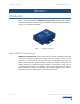
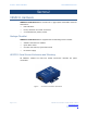
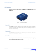
Section 1 - Introduction Vlinx VESR4x4 Serial Server SECTION 1 Introduction Thank you for purchasing a VESP211 Serial Server product! This product has been manufactured to the highest standards of quality and performance to ensure your complete satisfaction. Figure 1. A VESP211 Serial Server About VESP211 Serial Servers VESP211 Serial Servers connect serial devices (RS-232, RS-422 or RS-485) to Ethernet networks, allowing the serial device to become a node on the network.
Section 1 - Introduction Vlinx VESR4x4 Serial Server VESP211 Serial Server Model Numbering The VESP211 Serial Server family of products includes three models: VESP211-232, which uses a DB-9M connector and supports the RS-232 serial interface VESP211-485, which uses a pluggable, five-position terminal strip and supports the RS-485 serial interface VESP211 which uses a DB-9M connector and supports the RS-232, RS422 and RS-485 serial interfaces All models incorporate one serial connection and one
Section 2 - VESP211 Hardware Vlinx VESR4x4 Serial Server SECTION 2 VESP211 Hardware VESP211 Serial Servers are enclosed in a rugged panel mountable enclosure and feature: LED indicators Power, Ethernet and serial connectors A recessed Reset (mode) switch.
Section 2 - VESP211 Hardware Vlinx VESR4x4 Serial Server LED Indicators VESP211s have three LED indicators: a Ready LED, an Ethernet LED, and a Serial LED. Figure 3. Front Panel of the VESP211 Ready LED The Ready LED (green) blinks once per second if the system is operating correctly. If the LED is off, it indicates the system is not operating correctly (or that it is in Console Mode). Ethernet LED The Ethernet LED illuminates if the Ethernet port is connected when data is transmitted or received.
Section 2 - VESP211 Hardware Note: Vlinx VESR4x4 Serial Server LEDs on the serial server are also used to indicate various Reset modes, as described in the following section. Reset Switch A recessed momentary Reset switch is located on the side of the enclosure. To activate the switch, insert a small plastic tool through the hole in the enclosure and press lightly. Figure 4.
Section 2 - VESP211 Hardware Vlinx VESR4x4 Serial Server Using the Reset Switch to exit Console Mode Press and hold the Reset switch for two seconds, or remove power from the serial server, wait a few seconds, and turn the power on again. The LEDs go back to their normal states when the device resumes normal operation. Using the Reset Switch to Reload Factory Default Settings Hold the Reset switch for more than ten seconds.
Section 2 - VESP211 Hardware Vlinx VESR4x4 Serial Server VESP211-485 serial servers use five-position removable terminal blocks for RS-422 and RS-485 connections. Figure 6. Five-Position Pluggable Terminal Blocks Note: Refer to Appendix D for connection pin-outs. Power Connector VESP211 serial servers use a barrel jack connector for power. The connector accepts a 2.1 millimeter plug and requires 12 VDC at 2.5 W maximum. Figure 7.
Section 2 - VESP211 Hardware Vlinx VESR4x4 Serial Server Figure 8. VESP211 Enclosure with Panel Mount Bracket An optional DIN rail mount adapter is available from B&B Electronics. Page 14 of 66 Manual Documentation Number: VESP211-5011m www.bb-elec.com/ www.bb-europe.
Section 3 - Initial Setup and Connections Vlinx VESR4x4 Serial Server SECTION 3 Initial Setup and Connections This section describes how to setup and connect VESP211 Serial Servers. Note: In this section devices to be connected to the serial server’s serial connection are simply referred to as the “serial device”. Connecting the Power Supply Connect a DC power supply by plugging a 12 VDC power source into the barrel jack on the top of the serial server. The center connection must be positive (+).
Section 3 - Initial Setup and Connections Vlinx VESR4x4 Serial Server RS-485 The RS-485 interface supports 2-wire or 4-wire operation. When configured for 4-wire operation the connection supports two signal pairs: TDA (-), TDB (+), RDA (-), RDB (+) and GND. This makes full-duplex operation possible. The data lines are differential pairs (A & B) in which the B line is positive relative to the A line in the idle (mark) state. Ground provides a common mode reference.
Section 3 - Initial Setup and Connections Vlinx VESR4x4 Serial Server VESP211 Serial Server Configuration Connections VESP211 Serial Servers can be configured using several methods: Via the network using Vlinx Manager software Via the network using a web browser Via the serial port using Vlinx Manager software (Console Mode) Configuring via the Network using Vlinx Manager VESP211 Serial Servers can be configured over the network using Vlinx Manager software running on a networked PC.
Section 3 - Initial Setup and Connections Note: Vlinx VESR4x4 Serial Server For more information on how to use Vlinx Manager to configure your serial server, refer to Section 4: Configuring the Serial Server Configuring via the Serial Port using Vlinx Manager (Console Mode) Your serial server can be configured via the serial port using Vlinx Manager. To use this feature the serial port must be connected to the serial port of a PC (using a null modem cable). Figure 11.
Section 3 - Initial Setup and Connections Vlinx VESR4x4 Serial Server Figure 12. Direct IP and Virtual COM Port Connection In Virtual COM Port Mode a PC can communicate across the network to the serial server as if the serial ports on the serial server are the PC’s serial ports. When a virtual COM port is configured on the PC (using Vlinx Manager) a new COM port appears in the Device Manager. Windows programs using standard Windows API calls are able to interface to virtual COM ports.
Section 3 - Initial Setup and Connections Vlinx VESR4x4 Serial Server Installing and Starting Vlinx Manager Vlinx Manager is a Windows-based application used to configure serial servers. Install it on your PC from the included CD. Installation should launch automatically when the CD is placed in the CD-ROM drive. If it does not automatically launch, click Start on the Windows Desktop and, at the Run command, type the drive letter and Vlinx Manager.exe. Follow the prompts to install the software.
Section 3 - Initial Setup and Connections Vlinx VESR4x4 Serial Server Color Description Black Dark Blue Dark Green Dark Red A step in the discovery process. A device was not found. A device was found. An error occurred. If one or more devices are found, the discovery window closes automatically and the Configuration window appears. Page 21 of 66 Manual Documentation Number: VESP211-5011m www.bb-elec.com/ www.bb-europe.
Section 4 - Configuring the Serial Server Vlinx VESR4x4 Serial Server SECTION 4 Configuring the Serial Server Overview of the Vlinx Manager The Vlinx Manager configuration window includes three areas: Icons Serial Server Information Table Configuration pane Figure 15. Note: Page 22 of 66 Vlinx Manager Configuration Window The screen shots shown in this manual refer to the VESR901. Your screen will display the model name/number and serial number of your device.
Section 4 - Configuring the Serial Server Vlinx VESR4x4 Serial Server Icons Figure 16. Configuration Window Icons Open Cfg - choose a previously saved configuration file. Save Cfg - save the current configuration to a file. Server Search - initiate another search for servers.
Section 4 - Configuring the Serial Server Vlinx VESR4x4 Serial Server When a serial server's IP address is configured for a network that is not within the local network's range, the serial server's information is displayed in a different color (orange). Configuration Pane The configuration pane is essentially a web browser. Figure 18.
Section 4 - Configuring the Serial Server Vlinx VESR4x4 Serial Server 1. Double-click the row associated with the desired serial server. The Login page appears. 2. Type the password into the Password box. The password is blank by default. Figure 19. Login Page 3. Click Login. The General Configuration page appears.
Section 4 - Configuring the Serial Server Vlinx VESR4x4 Serial Server Figure 20. General Configuration Page Changing the serial server’s name: 1. Type the new name into the Serial Server Name text box. 2. Click Save. Changing the password: 1. Select the I want to change the password check box. Two text boxes appear. Figure 21. Changing the Password 2. Type the new password into both boxes 3. Click Save.
Section 4 - Configuring the Serial Server Vlinx VESR4x4 Serial Server Figure 22. Network Configuration Page Setting up Dynamic IP Addressing 1. Select the I want to use DHCP to setup the network check box. Setting up Static IP Addressing 1. Ensure the I want to use DHCP to setup the network box is un-checked. Figure 23. IP Address Settings 2. Type the IP Address, Subnet Mask and Default Gateway addresses in the appropriate boxes.
Section 4 - Configuring the Serial Server Vlinx VESR4x4 Serial Server Figure 24. Serial Port Configuration Page 1. Mode - select the type of serial connection (RS-232, RS-422, RS-485 2wire or RS-485 4-wire) required to connect the serial device to the serial server. 2. Baud Rate - select the Baud Rate (between 75 baud and 230,400 baud) required to communicate with the serial device connected to the serial server. 3.
Section 4 - Configuring the Serial Server Vlinx VESR4x4 Serial Server TCP Configuration TCP (Transmission Control Protocol) provides reliable connection-oriented network communication with error checking. In TCP mode the serial server can be configured as a client or a server. When you configure the serial server as a TCP client it initiates connections with a server on the network. You must set up the IP address and port number of the server that you want the client (serial server) to communicate with.
Section 4 - Configuring the Serial Server Vlinx VESR4x4 Serial Server 5. Select: at power up - if you want the serial server to always be connected when the serial port receives data - if you only want to establish a connection when there is data to be sent. Setting the serial server to operate as a TCP Server 1. Select TCP protocol. 2. Select to wait for connections (server). The configuration options change. The server IP address box disappears and the number of connections box appears. 3.
Section 4 - Configuring the Serial Server Vlinx VESR4x4 Serial Server You can also configure the serial server to receive from nodes on the network using the same list of configuration options. Figure 27. UDP Configuration Setting the serial server to use UDP 1. Select UDP protocol.
Section 4 - Configuring the Serial Server Vlinx VESR4x4 Serial Server If you selected: everyone on a specific UDP port (send broadcast), type the UDP port number into the This is the UDP port I want to send data to: box If you selected: only specific IP addresses (send unicast), type the IP addresses and port numbers into the These are the IP addresses I want to send data to: text boxes If you selected: only a range of IP addresses (send unicast range), type the ranges of IP addresses and port
Section 4 - Configuring the Serial Server Vlinx VESR4x4 Serial Server Figure 28. Note: VCOM Configuration Both the serial server and the computer must be configured for VCOM operation. To set up a virtual COM port on the computer, refer to the section on Adding Virtual COM Ports. 1. To enable VCOM operation, select VCOM protocol. 2. Click Save Setting up Paired Mode Operation Paired Mode enables two serial servers to operate across the network like a "wire replacement" between two serial devices.
Section 4 - Configuring the Serial Server Vlinx VESR4x4 Serial Server Figure 29. Paired Mode Configuration Setting the serial server to operate in Paired Mode as a client 1. Select Paired protocol. 2. Select to initiate connections (client) 3. Type the IP address and TCP port numbers of the server in the appropriate text boxes. 4.
Section 4 - Configuring the Serial Server Vlinx VESR4x4 Serial Server 3. Type the TCP port number to be used in the I want to wait for connections on TCP port number box. 4. Select the number of connections in the and limit the number of connections to drop down box. 5.
Section 4 - Configuring the Serial Server Figure 33. Vlinx VESR4x4 Serial Server Advanced Network Settings Window with nothing selected Configuring when connections will be forced closed 1. Select the I want to control when connections would be forced closed checkbox. The Network Watchdog and Serial Watchdog configuration boxes appear. Figure 34. Advanced Configuration - Forcing Connections Closed To close a connection if no data is received for a period of time 1.
Section 4 - Configuring the Serial Server Vlinx VESR4x4 Serial Server 2. Type the desired time period (in milliseconds) into the text box. Configuring when data packets are sent 1. Select the I want to control when data packets are sent over the network checkbox. Character Count, Forced Transmit, Intercharacter Timeout, Delimiter 1, Delimiter 2 and Delimiter Removal configuration boxes The appear. Figure 35.
Section 4 - Configuring the Serial Server Vlinx VESR4x4 Serial Server To wait until a specific amount of data is received on the serial port before sending it across the network 1. Select: I want to wait for a specific amount of data to be received by the serial port before sending it in the Character Count box 2. Type the desired number of characters into the text box. To force the serial server to send data received on the serial port within a specified length of time 1.
Section 4 - Configuring the Serial Server Vlinx VESR4x4 Serial Server To force the serial server to remove the delimiter characters from the data when it sends it on its serial port 1. Select: I want to remove the delimiter characters from the data before sending the data. Page 39 of 66 Manual Documentation Number: VESP211-5011m www.bb-elec.com/ www.bb-europe.
Section 4 - Configuring the Serial Server Vlinx VESR4x4 Serial Server Saving/Restoring the Configuration Settings When all configuration windows are complete the Save Configuration page appears. Figure 36. Save Configuration Page To save the configuration to the serial server, and re-boot it so that the configuration settings will take effect 1. Click Save. To restore the configuration settings that existed before beginning configuration 1. Click Restore Defaults.
Section 4 - Configuring the Serial Server Vlinx VESR4x4 Serial Server Figure 37. Add Virtual COM Port Dialog Box Using the drop down boxes you can select the serial server you want to map the virtual COM port to, the number of the serial port on the serial server and the COM port on the local computer. The information box displays the server name, its IP address, operating mode and TCP port. 1. On the Vlinx Manager window, click the Add VCOM icon. The Add Virtual COM Port dialog box appears. 2.
Section 4 - Configuring the Serial Server Vlinx VESR4x4 Serial Server Figure 38. Remove Virtual COM Port Dialog Box Using the drop down boxe you can select the virtual COM port on the local computer. The information box displays the server name, its IP address, operating mode and TCP port. 1. Click the Remove VCOM icon. The Remove Virtual COM Port dialog box appears. 2. Select the COM port number you want to remove from the local computer. 3. Click the Remove button.
Section 4 - Configuring the Serial Server Page 43 of 66 Vlinx VESR4x4 Serial Server Manual Documentation Number: VESP211-5011m www.bb-elec.com/ www.bb-europe.
Section 4 - Upgrading the Serial Server Firmware Vlinx VESR4x4 Serial Server SECTION 4 Upgrading the Serial Server Firmware Occasionally, updated firmware may become available for your serial server. The firmware can be upgraded using the Vlinx Manager software. The following procedure describes the firmware updating process: 1. Click the Firmware Upgrade button to open the Firmware Upgrade window. Figure 39.
Section 4 - Upgrading the Serial Server Firmware Vlinx VESR4x4 Serial Server To download the latest firmware files from an FTP site on the Internet 1. Click the Internet button at the bottom of the window. The Vlinx Manager connects to an FTP server on the Internet. 2. Click the Check for Updates button. Progress Bar and Progress Box display information about and progress of the download. To download the latest firmware files from a file 1. Click the Browse button to open an Open File dialog box. 2.
Section 7 - Diagnostics Vlinx VESR4x4 Serial Server SECTION 7 Diagnostics Clicking the Diagnostic icon opens the Diagnostics dialog box and enables you to check the operation of connected serial servers and VCOM ports on the local computer. The Computer Information box displays information about the type of network connections, the IP addresses, Subnet Masks and Default Gateways in use. Figure 40. Diagnostics Dialog Box Testing a Serial Server Connection 1. Click the Diagnostic icon.
Section 7 - Diagnostics Vlinx VESR4x4 Serial Server Figure 41. Testing a Serial Server Connection Testing a Virtual COM Port 1. Loopback the serial port (i.e. connect TD to RD) 2. Click the Diagnostics icon. The Diagnostics dialog box appears. 3. Select the option: a virtual communications port 4. In the drop down box select the specific COM port you want to check. 5. Click the Start button Information about the progress of the pinging process is displayed in the Test Progress box.
Section 7 - Diagnostics Vlinx VESR4x4 Serial Server Figure 42. Page 48 of 66 Testing a VCOM Port Manual Documentation Number: VESP211-5011m www.bb-elec.com/ www.bb-europe.
Section 8 - Description of Serial Server Properties Vlinx VESR4x4 Serial Server SECTION 8 Description of Serial Server Properties The following serial server properties are ordered alphabetically to assist you in finding the information you need. Baud Rate is the communication speed of the link between the serial server and the device attached to its serial port. Both these devices must be configured to operate at the same baud rate. Baud rate values range from 75 to 230,400 Baud.
Section 8 - Description of Serial Server Properties Vlinx VESR4x4 Serial Server Delimiter 1, Delimiter 2 and Delimiter Removal. Delimiters and Delimiter Removal enable you to control how characters received on a serial port are sent across the network. Delimiters are ASCII characters specified by the user when configuring the serial server. The serial server takes action when it recognizes the specified character(s) on its serial port. Delimiter 1 is a start delimiter.
Section 8 - Description of Serial Server Properties Vlinx VESR4x4 Serial Server Note 1: This product is factory defaulted to the DHCP mode. It is intended that your network’s DHCP Server provide the IP address assignment. If there is not a DHCP server on your network, the device will default to IP address 169.254.102.39. Note 2: A dynamic address assigned by the DHCP server may change if the server loses the Ethernet connection or power is removed.
Section 8 - Description of Serial Server Properties Vlinx VESR4x4 Serial Server 1. Method One: Change your PC Network to Match the Serial Server a. Open the network connection on your PC Figure 43. b. Click Internet Protocol (TCP/IP) and then click Properties. Change the parameters to the following: IP Address = 169.254.102.1 Subnet Mask = 255.255.255.0 Default Gateway = 169.254.102.100 Figure 44. c.
Section 8 - Description of Serial Server Properties c. Vlinx VESR4x4 Serial Server Enter Console Mode. Press and hold the serial server’s reset switch for 2 to 10 seconds. The LED indicators will respond as follows: Model Port 1 LED Port 2 LED Ready LED 1 Port 2 Port OFF OFF N/A ON ON OFF d. Release the Reset button. The Ready LED will blink once per second for 5 seconds. This indicates that the serial server is re-booting in Console Mode. e.
Section 8 - Description of Serial Server Properties Vlinx VESR4x4 Serial Server The MAC Address is a hardware level address of the serial server that cannot be changed. It is assigned in the factory. Every Ethernet device manufactured has its own unique MAC address. The MAC address of each serial server is printed on the device's label. The MAC address of each device is shown in the Serial Server Information Table.
Section 8 - Description of Serial Server Properties Vlinx VESR4x4 Serial Server kbaud over short distances (typically 50 feet). Typically uses DB-9 connectors but terminals are also used on VESP211 serial servers. RS-422 - Point-to-point communications using a transmit pair and a receive pair. RS-422 can operate at higher speeds and longer distances than RS-232. Typically uses two shielded twisted pairs and screw terminals but DB-9 connectors are also used on VESP211 serial servers.
Section 8 - Description of Serial Server Properties Vlinx VESR4x4 Serial Server For a Class D network (IP addresses 224.0.0.0 through 239.255.255.255) and Class E Networks (IP addresses 240.0.0.0 through 255.255.255.255) the subnet mask is ignored. VESP211serial servers come from the factory with a default subnet mask value of: 255.255.255.0 TCP (Transmission Control Protocol) provides reliable connection-oriented network communication with error checking.
Section 8 - Description of Serial Server Properties Page 57 of 66 Vlinx VESR4x4 Serial Server Both the serial server and the computer must be configured for VCOM operation. Virtual COM ports can be set up on the PC using the Vlinx Manager software. Manual Documentation Number: VESP211-5011m www.bb-elec.com/ www.bb-europe.
Section 9 - Appendix Vlinx VESP211 Serial Server SECTION 9 Appendix Appendix A: Default Server Settings Setting Server Name Serial Number Password DHCP IP Address MODEL NUMBER Printed on the label password field is blank from factory Enable Net Mask BASED ON DHCP SERVER If a DHCP assignment is not available, the device will default to 169.254.102.39 255.255.0.0 Gateway 169.254.1.1 Firmware Version X.X.X (Current Version) Hardware Version X.
Section 9 - Appendix Vlinx VESP211 Serial Server Appendix B: Product Specifications General Specifications Hardware and included accessories Device Optional Accessories Cable Configuration Options Via serial port CD Via network Software Environment Certifications Enclosure Power Supply Terminal Blocks Vlinx Manager for serial server configuration Operating Temperature Storage Temperature Operating Humidity Maximum Ambient Surrounding Air Temp UL 60950 FCC CE NEMA TS2 Rating Mounting Dimensions
Section 9 - Appendix Vlinx VESP211 Serial Server Controls, Indicators and Connector Specifications Switches Reset button Indicators Serial LED Ethernet LED Ready LED Connectors 10BaseT/100BaseTX Ethernet Serial DC Power Hold in for 0 to 2 seconds for hardware reset Hold in for 2 to 10 seconds for Console Mode (Do a hardware reset or recycle power to exit Console Mode) Hold in for more than 10 seconds to reset to factory defaults Color = Green On = Port open Blink = Data traffic Color = Yellow or Gre
Section 9 - Appendix Vlinx VESP211 Serial Server Network Specifications Memory I/P Port Addresses Network Communications Network Physical Layer Standards Protocols Supported Serial Memory Network Memory 5300 8888 LAN Ethernet IP Mode TCP/UDP UDP Connection Modes Client Connection Search Diagnostics Firmware Upgrade Character count Delimiters Timeouts 8 KB per port 4 KB Heartbeat & Configuration setting in TCP Mode (i.e. Pair Mode) VESP211 update 10/100 Mbps Auto-detecting 10BaseT or 100BaseTX IEEE 802.
Section 9 - Appendix Vlinx VESP211 Serial Server 60000/tcp This port is open when serial port 1 is configured for paired-mode server. These ports are used to transfer handshake line state and break state in paired mode configuration. These ports are open only if you configure the port for paired-mode server. Note that serial port 1 uses 60000/tcp, serial port 2 uses 60001/tcp, serial port 3 uses 60002/tcp and serial port 4 uses 60003/tcp.
Section 9 - Appendix Vlinx VESP211 Serial Server Appendix C: Dimensional Diagram Figure 45. Page 64 of 66 Dimensional Diagram of a VESP211 Serial Server (dimensions in inches & millimeters) Manual Documentation Number: VESP211-5011m www.bb-elec.com/ www.bb-europe.
Section 9 - Appendix Vlinx VESP211 Serial Server Appendix D: Connector Pinouts DB-9M Connnector DB-9M Pin RS-232 Direction (RS-232) RS-422/485 4-Wire RS-485 2-Wire 1 DCD Input RDA (-) --- 2 RD Input RDB (+) --- 3 TD Output TDB (+) Data B (+) 4 DTR Output TDA (-) Data A (-) 5 GND --- GND GND 6 DSR Input --- --- 7 RTS Output --- --- 8 CTS Input --- --- 9 --- --- --- --- Terminal Block Page 65 of 66 Terminal RS-422 RS-485 A TDA (-) Data A (-) B TDB
Section 9 - Appendix Vlinx VESP211 Serial Server Note 1: In the RS-422 mode, TX lines are outputs and RX lines are inputs. Connect the serial server TDB(+) line to the RDB(+) line of the serial device, and the serial server TDA(-) to the RDA(-) of the serial device. Note 2: Ground is signal ground and provides a common mode reference for the RS-422 Receiver and Transmitters.