Dual-Port Multi-Interface (RS-232/422/485) Ethernet Serial Server Model ESP902, ESP902E Documentation Number: ESP902-2303 International Headquarters B&B Electronics Mfg. Co. Inc. 707 Dayton Road -- P.O. Box 1040 -- Ottawa, IL 61350 USA Phone (815) 433-5100 -- General Fax (815) 433-5105 Home Page: www.bb-elec.com Sales e-mail: orders@bb-elec.com -- Fax (815) 433-5109 Technical Support e-mail: support@bb.elec.com -- Fax (815) 433-5104 European Headquarters B&B Electronics Ltd.
Table of Contents Chapter 1: INTRODUCTION................................................1 Features .................................................................................... 1 Communication Modes ............................................................ 2 Direct IP Mode........................................................................... 2 Virtual COM Mode..................................................................... 2 Heartbeat ...................................................
RS-232 Mode ............................................................................. 9 Default Setting .......................................................................... 9 Upgrade Mode......................................................................... 10 Console Mode ......................................................................... 10 Serial Connections ................................................................. 10 RS-232 Connections..........................................
MAC Address .......................................................................... 23 Link Status (Shown in Telnet or Console mode only) ........ 23 Server Serial Port (Select 1 or 2)........................................... 23 Baud Rate (Set for each port)................................................ 24 Data/Parity/Stop (Set for each port)...................................... 24 Flow Control (Set for each port)............................................ 24 Connection Mode (Set for each port) ...
Chapter 1: INTRODUCTION The VLINX Model ESP902 Dual-Port Ethernet Serial Server provides Ethernet to Serial connections for RS-232, RS-422 or RS-485 devices. The serial ports can be accessed over a LAN/WAN using “Direct IP Mode”, “Virtual COM Port”, or “Paired Mode” connection. The 10/100 Mbps Ethernet connection autoselects 10BaseT or 100BaseTX and indicates the type of connection with a bicolor link light.
Communication Modes The ESP902 enables communication with serial devices over a LAN or WAN. Serial devices are no longer limited to a physical connection to the PC COM port. They can be installed anywhere on the LAN using TCP/IP or UDP/IP communications. This will allow traditional Windows PC software access to serial devices anywhere on the LAN/WAN network.
Heart Beat The Heart Beat protocol connection provides a reliable communications connection in Virtual COM port mode or with paired (tunneling) mode. This feature restores the connections if communications are temporarily lost at either end due to loss of power or Ethernet connection. Without this feature a device that loses a connection and stops communicating would not be able to reconnect without human attention to correct the problem.
Step 1: Decide which method to use for configuration and operation. If using the Console mode for setup, refer to the Console mode section, Chapter 9, and Chapter 5, then power up the unit. Step 2: Attach the ESP902 to your network or computer Ethernet port. You can connect your serial devices now if needed. If using Telnet for setup, refer to the Console mode section, Chapter 9, and Chapter 5, then power up the unit.
Specifications Serial Memory: 8K bytes per port LAN: 10/100 Mbps Auto-detecting 10 BaseT or 100 BaseTX Protocols TCP, IP, ARP, DHCP, Telnet, HTTP, UDP, ICMP Indicators Power – Red LED Link – Yellow or Green (10BaseT or 100 BaseTX) Ready – Flashing Green Connectors Ethernet: single RJ-45 female Serial: two - 9 pin D-type male (DB9M) ESP Port 1 is switch selectable as RS-232/422/485 ESP Port 2 is always RS-232 DC: ultra-miniature phone jack (2.
Hardware and Included Accessories ESP902 Serial Server module Power Supply: 12VDC/500mA (tip positive/sleeve negative) Area Dependent: US power plug (120VAC/60Hz) or Euro or UK power AC plug (220/240VAC/50Hz) Manual (paper copy of this manual) CD-ROM disc with software for Windows 98/ME/2000/XP/NT 4.
Chapter 2: HARDWARE This section covers indicators, switch settings and connections. Side View – when vertical mounted Light Power Link Ready Indication Red - Power is applied Yellow – 10 BaseT Ethernet or Green – 100 BaseTX Ethernet connection established Flashing Green – system is ready Ethernet Connection A straight-through RJ45 (male) Ethernet cable can be used to connect the serial server to an Ethernet hub, switch, or wall plate.
Top View DC –In Connect the included power supply here, and then plug the supply in. When power is applied, the Red power light will illuminate. The tip of the power plug is positive, sleeve is negative. The standard 12VDC/500mA power supply for US shipment is 120VAC/60Hz, for Europe or UK it will be 230VAC or 240VAC/50Hz. Reset Button Resets the unit similar to removing/applying power. The Reset Button is recessed to avoid accidental operation.
RS-485 Mode The RS-485 mode supports the Transmit and Receive Channels using 2-wire half-duplex operation. The data lines are differential with the Data B line positive relative to Data A in the Mark state. Ground provides a common mode reference. Refer to the Pin-out table for connections. Internal Setting To Select RS-485 Bias You can select RS-485 Receiver Biasing from the ESP902 if your network doesn’t supply any.
Upgrade Mode You can install newly revised firmware for the ESP902 using RS-232 connections from a PC, through the ESP Manager or through the Virtual COM port. See Chapter 8 for details. Console Mode The Console mode provides access to the configuration menu using RS-232 connections. Connect a null modem crossover cable between the multiinterface port and one of the computer’s RS-232 serial ports.
The ESP902 has two DB-9 male connectors. ESP Port 1 - Multi-interface, dip-switch selectable RS-232, RS-422 or RS-485. ESP Port 2 - RS-232 only . RS-232 Connections In the RS-232 mode, the ports are configured as DTE (Data Terminal Equipment) like a computer. ESP902 to device connections are the same. When connecting to a PC or another DTE device, use a null modem crossover cable. When connecting to a DCE device that can normally be plugged into a PC, use a straight through cable.
RS-422 Connections In the RS-422 mode, TXD lines are outputs, RXD lines are inputs. Connect the TXDB(+) line to the RXDB(+) line of your device, and the TXDA(-) to the RXDA(-) of your device. If Flow Control is set for RTS/CTS, connect the RTSB(+) to CTSB(+) of your device and RTSA(-) to CTSA(-) of your device. Connect from CTSB(+) to RTSB(+) of your device and from CTSA(-) to RTSB(+) of your device.
RS-485 Connections Some RS-485 devices are marked opposite from the RS-485 standard which defines the Data B line as positive relative to Data A during a Mark state before enabling the transmitter, and after transmitting before tri-stating. If the RS-485 devices don’t respond, try swapping the Data B and Data A lines. If you want to connect 4-Wire RS-485 devices, you can use the RS-422 Mode provided that the ESP902 will be connected as a Master in a single master system.
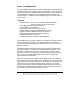
Chapter 3: INSTALL VLINX ESP SOFTWARE The Windows based ESP Manager and Virtual COM port software makes configuration fast and easy. We recommend installing the Software to configure the ESP902 unless you are not using Windows. To install the ESP Manager, Install Virtual Com, Uninstall Virtual COM programs: Inserting the VLINX CD in the CD-ROM will automatically launch the Install Shield Wizard. To manually start the software installation, select the Start button on the desktop.
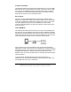
When Choose Destination Location appears, Click Next. The installation progress will be shown until complete.
Select Finish when the Install Shield Wizard Complete appears. After Finish, the Install window closes. You can now start the ESP Manager software, use Start, Programs. B&B Electronics. VLINX ESP Servers, VLINX ESP Manager. If you have not already connected the ESP902 to your network or to the Ethernet port on your computer, connect it, then apply power.
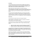
Chapter 4: USING ESP MANAGER The ESP Manager software performs several functions, Search LAN for ESP Servers, Configure ESP Server, Uninstall Virtual COM port, Virtual COM Configuration, and Upgrade Firmware. Connect the ESP902 to the LAN or to the Ethernet port on your computer. Use an Ethernet Crossover Cable if connecting directly to your computer LAN card. Apply power. The Red Power indicator will light, the Link indicator lights when an Ethernet connection is made, and the Ready indicator will flash.
In the left side of the ESP Manager Window these items are shown: Firmware Upgrade This is used when downloading new firmware to the ESP Server. See Chapter 8 Virtual COM Configuration Can be used to change the Virtual COM Settings, IP address, Port #, Flow Control. Searching Server Can be used to find ESP Servers on the network. Uninstall Virtual COM Shown in Windows 2000 and XP Manager. Uninstall for Windows 98, and ME located in Start/program/B&B Electronics/Vlinx/ files.
COM Name The mapped COM number is shown. Status The Status indicates the Mapped (Virtual) COM port condition. “Not Connected” is shown when a program does not have the port Open. “Connected” is shown when that Mapped port is Open for use. Server Properties Screen Highlight the serial server in the Manager Server window, double-click to open. The Server Properties screen is used to Configure and store the Server settings. Details for setting Properties are shown in the next chapter.
After Configuring as needed, click Update to Store the Configuration in the Server. After storing the configuration, and answering Yes to Restart, the server is automatically reset. Repeat Search to verify changes. Continued in next chapter.
Chapter 5: SERVER PROPERTIES CONFIGURATION The VLINX Serial Server can be configured one of three ways: using the ESP Manager Software, Telnet, or Console mode. The Server Properties Configuration screen shown in the previous chapter displays a box for each property, Telnet or Console configuration will show similar configuration items. In the ESP Manager you can use the mouse to select the property and parameters for each property.
Server Name You can enter a new Server Name of up to 16 characters. If you have more than one ESP901 or ESP902 Server on the LAN we recommend that you assign a new name to each. When the ESP Manager finds ESP Servers on the LAN it displays the server name and IP Address allowing the user to distinguish between ESP902’s. Password Entering a password activates a security feature on the serial server. Once a password is entered it will be required to access the menu and make changes.
IP Address Assign a static IP address using this property. A static IP address is retained and used each time the server is powered up or starts/restarts. Software or hardware attempting to access the server will need to use the static address to access the server. The Network Administrator will assign/establish the static address or group of addresses to be used. The default IP address is shown on a label affixed to the bottom cover. Such as IP 192.168.0.
the settings for the port shown are stored. Using Telnet or Console mode, Save stores settings for both ports. Baud Rate (Set for each port) The serial port baud rate on the ESP902 must match the serial baud rate of the connected device unless using Virtual COM mode. In Virtual COM mode the software program will establish serial settings. Use the arrow keys to change the setting to the desired baud rate.
In all modes of operation, Direct IP or Virtual Com, the port number set in the ESP902 menu must match the Virtual COM and socket software port settings. As an example the Virtual COM default setting is TCP/UDP Port 4000. If the port # property is changed to 4001, then the Virtual COM TCP/UDP Port will have to be changed to 4001. The ESP Manager or Telnet/Console configuration can change the setting for the hardware.
Status displays how many Ethernet packets and serial bytes are transmitted and received. A refresh button is available to update the displayed figures.
Chapter 6: INSTALLING VIRTUAL COM PORT The Virtual COM Port software enables Windows based applications to use the serial port on the ESP902 server as a COM port or to use standard Windows API calls for COM port access. The Install Virtual COM port software adds a ESP902 (COM#) port to the computer which shows up in the Device Manager. The COM number can be selected from a list of available numbers. For example, in a computer already having a COM1 and COM2, COM3 to COM 254 is available for the ESP902.
After the COMInst window opens, select the desired COM # in the Map To: options. Windows XP provides a notice concerning Windows Logo testing for XP. This XP feature simply indicates that these drivers have not yet undergone the Microsoft testing procedures required to use the Windows XP Logo on the packaging. Driver compatibility is not affected. Select “Continue anyway” to proceed with the installation.
Note: Your PC may have hardware COM ports and devices such as a Modem, IR port or USB based COM ports which are not currently connected. You may want to select a COM number above COM4 if problems occur. The default Flow Control setting is None. RTS/CTS can be selected if used by the application program and serial hardware. The ESP Server must be set to match. The settings of the Virtual COM port in the Device Manager and the ESP902 Configuration menu must match.
Select the Configuration or Port Settings tab. This screen lets you change the Settings if needed. Use Cancel if you don’t want to change any settings. Use OK to change the settings. Use Refresh in the Device Manager if your version of Windows doesn’t auto refresh.
Chapter 7: REMOVING A VIRTUAL COM PORT The ESP902 Management software Uninstall Virtual COM port feature will remove the mapped COM port in the Device Manager of Windows 2000 and XP operating systems. It may also be removed in the Device Manager of Windows 98, ME, NT, 2000, and XP. Windows 98 users will also find a Remove Virtual COM feature in the programs file. Removing the Virtual COM port with the ESP902 Management Software 1.
Removing the Virtual COM Port using Device Manager The screen shots were taken from a Windows XP operating system 1. On the Desktop select Start/Settings/Control Panel. Select the system icon when the manager window opens.
2. Select Device Manager in the Systems Properties window. In Device Manager window select the + next to Ports (COM LPT) to expand. 3. Highlight ESP902 (COM #) to be removed, go the Action tab at the top of window and select uninstall. A confirm Device Removal window will appear. Select OK to procedure. 4. The ESP902 COM # will be removed and the Device Manager window will refresh and display the remaining COM ports.
Chapter 8: UPGRADE MODE New ESP902 firmware may become available through our web site for installation into the ESP902. The software can be downloaded to the ESP902 using either the Virtual COM or hardware COM port. Using Virtual COM or Serial Connections Make a folder to receive the firmware file. Download the compressed software file from our website to your folder. Unzip or expand the file into the (.hex) format so it will be ready to download to the ESP902.
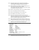
Select Browse, locate the folder where you placed the firmware .hex file, select it, Open, and then select the upgrade button. In the Serial Port selection options select the COM port number used to connect to the ESP902. If using the Virtual COM port select that number. Next a serial menu is shown so you can match the Upgrade mode settings to ESP Server serial settings (which you noted in Server Properties). The settings must match or the upgrade will fail.
Upgrade progress will be shown until the Upgrade was successful message is shown. Select and exit from the Manager software.
Chapter 9: CONSOLE MODE SETUP Before the ESP902 is installed on a LAN the Console Mode can be used to change the settings from the Defaults. Set the 3 - ESP902 switches to the “ON” position. Connect a null modem cable between the Multi-interface serial port (ESP Port1) on the Server and the COM port on the Computer. See Chapter 5 for details of each Server Property Setting. Apply power to the ESP902. The power and ready LED will light.
The restart message will appear. Select Yes to save changes. This is necessary to write the settings to the server. To view the changes press the space bar. The screen will reappear. If you assign a password to the server, you will need to supply it before you can view the Configuration screen. When you access the server with a password and make no changes, Reset to end before Disconnect.
APPENDIX A: RS-232, RS-422 LOOPBACK CONNECTIONS For Transmit and Receive loopback, connect only those lines. When Flow Control setting on the Serial Server is set for RTS/CTS, those lines must be looped. Usually DTR and DSR must also be looped. The Flow Control setting for the program must match the Server settings. The CD connection is needed by some terminal programs to simulate Carrier.
APPENDIX B: RS-232 CONNECTIONS RS-232 Signal Name Carrier Detect Receive (Rx) Data Transmit (Tx) Data Data Terminal Ready Signal Ground Data Set Ready Request To Send Clear To Send Ring Indicator Documentation Number: ESP902-2303 Manual RS-232 DTE In In Out Out --In Out In In DCD RXD TXD DTR GND DSR RTS CTS RI DB9M Pin 1 2 3 4 5 6 7 8 9 Appendix B B&B Electronics Mfg Co Inc – 707 Dayton Rd - PO Box 1040 - Ottawa IL 61350 - Ph 815-433-5100 - Fax 815-433-5104 B&B Electronics Ltd – Westlink Commercial Pa
RS-232 CONNECTIONS (cont’d.) Refer to Chapter 2 for more information.
APPENDIX C: RS-422 CONNECTIONS RS-422 Connections RS-422 Signal Name Receive Data A (−) Receive Data B (+) Transmit Data B (+) Transmit Data A (−) Signal Ground Clear to Send A (−) Clear to Send B (+) Request to Send B (+) Request to Send A (−) RS-422 Direction In In Out Out --In In Out Out Documentation Number: ESP902-2303 Manual RXDA (−) RXDB (+) TXDB (+) TXDA (−) GND CTSA (−) CTSB (+) RTSB (+) RTSA (−) DB9M Pin 1 2 3 4 5 6 7 8 9 Appendix C B&B Electronics Mfg Co Inc – 707 Dayton Rd - PO Box 1040 -
RS-422 CONNECTIONS (cont’d.) Refer to Chapter 2 for more information.
APPENDIX D: RS-485 CONNECTIONS RS-485 Signal Name Data B (+) Data A (−) Signal Ground RS-485 Direction In/Out In/Out --- DATA B (+) DATA A (−) GND DB9M Pin 3 4 5 Refer to Chapter 2 for more information.