INSTRUCTION MANUAL Universal sensor switching module 230 V version with Housing 0141 0316-142 September 2011 Technical changes reserved B+B Thermo-Technik GmbH | Heinrich-Hertz-Str. 4 | D-78166 Donaueschingen Fon +49 771 83160 | Fax +49 771 831650 | info@bb-sensors.com | bb-sensors.
INSTRUCTION MANUAL Universal sensor switching module 230 V version with Housing Contents 1. General dangers and precautions 1.1. Instructions regarding documentation 1.2. Safety instructions 2. Description 2.1.Functional description 2.2. Range of available probes 2.2.1. Humidity probe 2.2.2. Conductance probe 2.2.3. Light intensity probe 3. Technical data 4. Ordering information 5. Assembly, adjustment and configuration 5.1. Electrical connection 5.1.1. Safety instructions 5.1.2. Probes 5.2.
INSTRUCTION MANUAL Universal sensor switching module 230 V version with Housing 1. General dangers and precautions 1.1. Instructions regarding documentation Please carefully read the following instructions before putting into operation! The symbols used in the operating manual are to make you careful, before hand, regarding safety considerations and dangers. But all these symbols cannot substitute the text of the associated safety instructions in any way.
INSTRUCTION MANUAL Universal sensor switching module 230 V version with Housing 2. Description 2.1. Functional description The universal sensor-switching module is suitable as a two-point regulator for a wide variety of sensors and industrial probes. A suitable sensor is connected at the input for sensing the parameter which is to be regulated. The relay mounted on the PCB gets triggered as per limit settings done through a potentiometer.
INSTRUCTION MANUAL Universal sensor switching module 230 V version with Housing 2.2. Range of available probes The probes described below are available as accessories. The probe is provided with a 1 m long connection cable, PG-threads for mounting of housing and a ready made RJ12 plug connector. All commercial grade industrial probes with voltage and current output can also be operated with the device. 2.2.1.
INSTRUCTION MANUAL Universal sensor switching module 230 V version with Housing 3. Technical data General Operating voltage Type –230V (156530) Operating voltage Type –MOD12V (156503) Operating voltage Type –MOD24V (156517) Time delay switch Relay Surge suppression Dimensions Sensors DC Impedance input Voltage/Current input AC Impedance input Switching input 230 VAC/5 VA max. 12 V..15 V DC 65 mA max. 11 V..14 V AC 80 mA max. (without probe) 22 V..28 V DC 45 mA max. 15 V..25 V AC 60 mA max.
INSTRUCTION MANUAL Universal sensor switching module 230 V version with Housing 5. Assembly, adjustment and configuration 5.1. Electrical connection 5.1.1. Safety instructions Caution! Touching the high voltage parts may lead to fatal dangers. The mounting and maintenance operations should be carried out by only trained personnel, who are authorized on the basis of technical training in this field.
INSTRUCTION MANUAL Universal sensor switching module 230 V version with Housing 5.4.1. Operating voltage 12V/24V-AC/DC Model: The operating voltage is connected at the terminals “SUPPLY VOLTAGE“. The rating of nominal voltage is mentioned on the PCB, under the voltage connection and also on the relay and must be maintained as per specifications on the data sheet in order to ensure an error free functioning. A too high operating voltage can lead to damage of the device.
INSTRUCTION MANUAL Universal sensor switching module 230 V version with Housing 6. Technical appendix 6.1. General instructions The technical appendix is useful for persons with adequate knowledge of electronics. The applicable safety regulations shall be duly followed! Connection and mounting work shall be carried out only after switching off the voltage supply. The following instructions help in connection of your own probes at the input socket of module.
INSTRUCTION MANUAL Universal sensor switching module 230 V version with Housing Configuration of switching input socket (RJ12) Pin 1 Function +5 V Description Operating voltage 5 V, stabilized 2 GND Device ground 3 INPUT Input (Switch contact) 4 +12..24 V Operating voltage 12...24 V, not stabilized 5 GND Device ground 6 GND Device ground View of contacts on the plug! Adjustment and configuration In switching input, only switching polarity can be configured.
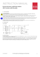
INSTRUCTION MANUAL Universal sensor switching module 230 V version with Housing 6.3. Impedance input Circuit diagram Functional description The impedance input is especially suitable for electrolytic type of sensors like conductance probes and level indicators, foam sensor, humidity and dew formation sensors, material moisture content probe or water/leakage probe. The operating principle is based on an AC voltage measurement that prevents the measuring current from creating electrochemical effects.
INSTRUCTION MANUAL Universal sensor switching module 230 V version with Housing Configuration of input socket RJ12 Pin Function Description 1 +12..24 V Operating voltage 12..24 V 2 AC OUT AC output 3 CAP GND Capacitive ground 4 SENS IN Evaluation input 5 CAP GND Capacitive ground 6 GND Device ground View of contacts on the plug! Adjustment and configuration For impedance input, the switching polarity can be configured with the three pin terminal strip below input.
INSTRUCTION MANUAL Universal sensor switching module 230 V version with Housing 6.4. Analog input Circuit diagram Functional description The analog input is to be adapted over a pin contact strip for various types of sensors and industrial probes. In order to also use resistive sensors as probes, there is possibility of applying the reference voltage to the sensor through a configurable preset resistor, which works as a voltage divider.
INSTRUCTION MANUAL Universal sensor switching module 230 V version with Housing Configuration of analog input socket RJ12 Pin Function Description 1 +5 V Operating voltage 5 V 2 +12..24 V Operating voltage 12..24 V 3 NC Unoccupied 4 ANA INP Evaluation input 5 GND Device ground 6 GND Device ground/Shielding View of contacts on the plug! Adjustment and configuration For impedance input, the switching polarity can be configured with the three pin terminal strip below input.
INSTRUCTION MANUAL Universal sensor switching module 230 V version with Housing Mode of operation Sketch 1 Description Impedance input 100 k: All such components are suitable as sensors in which the resistance value is a function of the measured parameter e.g. LDRs (photo resistors) or NTCs (temperature sensors). The sensor with a resistance value of 0..100 k Ohm is connected at the RJ12 socket between ANA INP (pin 3) and GND (pin 2). Same as (1), however for sensors with resistance value of 0..
INSTRUCTION MANUAL Universal sensor switching module 230 V version with Housing 6.5. Time delay switch A digital time delay switch is integrated in the module, which can be adjusted over a wide range. The applications are many, for example, for direct triggering of cooling units or pumps, in order to avoid short time running time of the units. The time delay switch ensures that the load remains switched on for a certain extra time period even after the switching criterion is not fulfilled further.
INSTRUCTION MANUAL Universal sensor switching module 230 V version with Housing 7. Guarantee Hearty congratulations on the purchase of this high quality product! The quality of our products is constantly monitored within the framework of our Quality Management systems as per ISO 9001 standards.