Dryer DA 475 Gas Installation / Maintenance And Part Manual ! """# $ $% &' $
Table of Contents Section 1 Important Information A. Receiving and Handling B. Safety Precautions 2 3 Section 2 Specifications/Component Identification A. Specification (Gas and Steam Model) Component Identification Installation Procedures A. Reassembly of Dryer B. Location Requirements C. Fresh Air Supply D. Exhaust Requirements E. Compressed Air Supply F. Electrical Information G. Steam Information H. Preparation For Operation/Start up 5 5 6 8 9 10 11 12 14 15 17 23 Section 4 Routine Maintenance A.
SECTION 1 IMPORTANT INFORMATION A. RECEIVING AND HANDLING The dryer is shipped in a protective stretch wrap cover with protective cardboard corners and top cover (or optional box) as a means of preventing damage in transit. Upon delivery, the dryer and/or protective packaging, and wooden skid should be visually inspected for shipping damage. If any damage whatsoever is noticed, inspect further before delivering carrier leaves. Dryers damaged in shipment: 1.
B. SAFETY PRECAUTIONS WARNING: For your safety, the information in this manual must be followed to minimize the risk of fire or explosion or to prevent property damage, personal injury, of loss of life. 1. Do not store or use gasoline or other flammable vapors and liquids in the vicinity of this or any other appliance. 2. Purchaser / user should consult the local gas supplier for proper instructions to be followed in the event the user smells gas. The instructions should be posted in a prominent location.
8. Remove articles from the dryer as soon as the drying cycle has been completed. WARNING: Articles left in the dryer after the drying and cooling cycles have been completed can create a fire hazard. 9. Do not operate steam dryers with more than 125 PSI steam pressure. Excessive steam pressure can damage steam coil and / or harm personnel. 10. Replace leaking flexible steam hoses or other steam fixtures immediately. Do not operate dryer with leaking flexible hoses. Personal injury may result. 11.
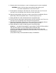
SECTION 2 SPECIFICATIONS / COMPONENT IDENTIFICATION A. SPECIFICATIONS (Gas and Steam Models) Maximum Capacity (Dry Weight) Minimum Capacity (Dry Weight) Basket Diameter Basket Depth Basket Motor Door Opening (Diameter) Door Sill Height From Floor Basket Volume Voltage Available Heat Input Gas Blower Motor, Approx. Weight Airflow Gas Inlet Size Voltage Available Blower Motor Approx.
B.
(
SECTION 3 INSTALLATION PROCEDURES M i cro P ro cesso r Con t rol abc def 1 l m no 3 4 tu v w xy z 6 c hi START 2 p q rs 5 SIN GL E CYCL E 7 8 ENTER 9 DO W N STOP
INSTALLATION PROCEDURES Installation in a proper location should be performed by competent technicians in accordance with local and state codes. A. REASSEMBLY OF DRYER IMPORTANT: Always keep the basket (tumbler) section of the dryer in an upright position when moving it. The dryer can be shipped in two (2) ways: as a complete unit fully assembled and ready for hookup or in two (2) pieces with the middle frame separated from the base. At installation, the middle frame will be lifted onto the base.
B. LOCATION REQUIREMENTS The model DA-475 dryer requires 20-inches and 20-inches of space on each side of the dryer and 24-inches of space behind the unit for ease of maintenance. A minimum of 20-inches must be allowed between the top of machine dryer the ceiling The dryer must be leveled for proper operation. If shimming is required put metal shims, which are the same size as the base feet under the base feet. The dryer must be lagged to the floor.
C. FRESH AIR SUPPLY When the dryer is operating, it draws in room air, heats it, passes this air through the basket (tumbler), and exhausts it out of the building. Therefore, the room air must be continually replenished from the outdoors. If the make-up air is inadequate, drying time and drying efficiency will be adversely affected. Ignition problem and sail switch “fluttering” problems may result, as well as premature motor failure from overheating.
D. EXHAUST REQUIREMENTS 1. General Exhaust Duct Work Information Exhaust duct work should be designed and installed by a qualified professional. Improperly sized duct work will create excessive back pressure which results in slow drying, increased use of energy, over-heating of the dryer, and shutdown of the burner by the airflow (sail) switches, burner hi-limits, or basket (tumbler) hi-heat thermostats.
Outside Duct Work Protection To protect the outside end of horizontal duct work from the weather, a 90o elbow bent downward should be installed where the exhaust exits the building. If the duct work travels vertically up through the roof, it should be protected from the weather by using a 180 o turn to point the opening downward. In either case, allow at least twice the diameter of the duct between the duct opening and the nearest obstruction.
E. COMPRESSED AIR SUPPLY A clean, dry, regulated supply of 80 psi compressed air must be supplied to the dryer. The connection size is 1/2-inch N.P.T. No air filtering or pressures regulating devices are provided with the dryer. 1.GAS DRYERS: The air line supply connection is made into the 1/2-inch N.P.T.
F. ELECTRICAL INFORMATION 1. Electrical Requirements It is your responsibility to have all electrical connections made by a properly licensed and competent electrician to assure that the electrical installation is adequate and conforms with local and state regulations or codes. In the absence of such codes, all electrical connections, material, and workmanship must conform to the applicable requirements of the national electrical code ANSI/NEPA NO. 70-latest edition.
3. ELECTRICAL CONNECTIONS NOTE: A wiring diagram is included with each dryer and is affixed to the panel inside the right side control cabinet. The only electrical input connections to the dryer are the 3-phase (3 ) power leads (L1, L2 and L3), GROUND, and in the case of 4 wire service, the neutral. These electrical connections are made at the power distribution block located in the left side control cabinet.
G. STEAM INFORMATION It is your responsibility to have All steam plumbing connections made by a qualified professional to assure that the installation is adequate and conforms with local and state regulations or codes. IMPORTANT: Failure to comply with the requirements stipulated in the manual can result in component failure, which will VOID THE WARRANTY. NOTE: The DA-475 is manufactured with a pneumatic (piston) damper system, which requires an external supply of air (80 psi +/- 10 psi).
E. Install an inverted bucket steam trap and check valve at least 12 inches below steam coil as close to the coil as possible. F. A vacuum breaker should be installed in the piping. This will prevent the condensing steam from causing a vacuum inside the coil and possibly damaging the coil. G. The supply and return lines should be insulated. This will save energy and provide for the safety of the operator and maintenance personnel. H.
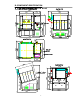
3. STEAM DAMPER AIR SYSTEM CONNECTIONS The DA-475 is manufactured with a pneumatic (piston) damper system, which requires an external supply of compressed air. The air connection is made to the steam damper solenoid valve which is located on the outer top, at the rear left hand corner of the dryer. A. AIR REQUIREMENTS Compressed Air Supply Normal Minimum Supply Maximum Supply Air Pressure 80 psi 70 psi 90 psi B. AIR CONNECTION Air connection to system --- ½ -inch N.P.T. C.
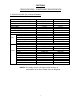
4. STEAM DAMPER SYSTEM OPERATION The DA-475 Steam damper allows the coil to stay constantly charged eliminating repeated expansion and contraction. When the damper is opened, the air immediately passes through the already hot coil, providing instant heat to start the drying process. When the damper is closed, ambient air is drawn directly into the basket (tumbler), allowing a rapid cool down. Diagram 1 shows the damper in the heating (open) mode, allowing heat into the basket (tumbler).
H. PREPARATION FOR OPERATION/START-UP The following items should be checked before attempting to operate the dryer: 1. Read and follow All “caution”,“warning”and“direction” labels attached to the dryer. 2. Check incoming supply voltage to be sure that it is the same as indicated on the dryer data label affixed behind the right control box door. In the case of 208 VAC or 230/240 VAC, the supply voltage must match the electric service exactly. 3.
SECTION 4 ROUTINE MAINTENANCE A. CLEANING A program and/or schedule should be established for periodic inspection, cleaning and removal of lint from various areas of the dryer, as well as throughout the duct work system. The frequency of cleaning can best be determined from experience at each location. Maximum operating efficiency is dependent upon proper air circulation. The accumulation of lint can restrict this air flow.
STEAM DRYERS ONLY Clean the steam coil lint screen located on top of the steam coil. (This may have to be done more frequently.) MONTHLY Apply a high-temperature grease to the four (4) 50 mm. diameter tumbler drive shaft plummer block bearings. Use Shell Alvania # 3 grease or equivalent. Retighten set screws in the collars of the four (4) 50 mm. diameter tumbler drive shaft bearings. Apply a high-temperature grease to the two (2) 55 mm. diameter blower drive shaft pillow block bearings.
NOTE: A back draft damper that is sticking partially closed can result in slow drying and shutdown of the heat circuit safety switches or thermostats. NOTE: When cleaning dryer cabinet(s), avoid using harsh abrasives. A product intended for the cleaning of appliances is recommended. B. ADJUSTMENTS 7 DAYS AFTER INSTALLATION AND EVERY 6 MONTHS THEREAFTER Inspect bolts, nuts, screws (bearing set screws), non-permanent gas connections (unions, shut-off valves, orifices, and grounding connections).
SECTION 5 WARRANTY INFORMATION A. WARRANTY For a copy of the commercial warranty covering your particular dryer(s), contact the distributor from whom you purchased the equipment and request dryer warranty form. NOTE: Whenever contacting the factory for warranty information, be sure to have the dryer’s model number and serial number available so that your inquiry can be handled in an expeditious manner. B.
SECTION 6 COMPONENT SYSTEM DESCRIPTIONS A. BASKET/TUMBLER DRIVE SYSTEM The basket (tumbler) is supported and driven by eight (8) 11-inch diameter drive wheels. Two (2) of these wheels are attached to 50 mm. diameter idler shaft, while the other two (2) are attached to a 50 mm. diameter drive shaft. Each of the wheels is fastened to the shafts by a keyless locking bushing. The trantorque is made up of three pieces: an inner collar,an outer sleeve, and a locking nut.
D. SAFETY DEVICES 1. Load Door Switches There are two (2) of these switches located under the main loading doors. These switches Ensure that the doors are closed before the dryer can start. If the dryer is started when the load doors are open, the microprocessor controller (computer) L.E.D. display will show “door” 2. Lint Basket Switch This switch ensures that the lint basket is closed be before the dryer can start. This switch is located at the front of the dryer at the right side of lint basket.
On a call for heat, a 24-volt signal is applied to the 3-way/2-position solenoid valve. This signal switches the valve so that compressed air is sent to the piston. The piston rod extends, pushing the hinged steam damper plate to the open position. This allows room air to be drawn through the hot steam coil and then through the basket (tumbler).
F. DRIVE SYSTEM SOFT START The DA-475 dryer is equipped with either a Series 154-A11NB OR 21B soft start control. ALL soft start controls are factory preset. Re-adjustment should not be necessary. 1. Series 154-A11NB OR 21B Drive System Soft Start Wiring The Series 154-A11NB OR 21B is a motor controller and is used with an electromechanical motor starter. The controller is wired after the motor starter as shown in the illustration below.
ACHIEVED. Set Up The single adjustment on the Series 154-A11NB OR 21B Determines the amount of starting voltage First applied to the motor. When rotated fully Counterclockwise, the lowest starting Voltage is obtained. As the adjustment is Rotated clockwise, the starting voltage is Increased. When rotated fully clockwise, The controller will produce approximately An across the line start. The motor will Receive full voltage within about one half (1/2) second.
2. Series 154-A11NB OR 25 Drive System Soft Start The soft start mechanism is simply a voltage-limiting device. Therefore, to be capable of seeing just what is happening, connect the leads of a voltmeter to connections T2 and T3, as shown in Figure 1 Initial starting voltage should be 60 percent to 65 percent of motor nameplate voltage.
3. Adjustments for reduced voltage soft controllers This procedure to be used with ALL Series 154-A11NB OR 21B OR 25 control styles. To properly adjust a soft start controller to give a satisfactory start, two characteristics Of the motor and load must be considered. The frictional load determines the amount Of torque required to break-away or obtain initial movement of the motor and load.
SECTION 7 TROUBLESHOOTING IMPORTANT: YOU MUST DISCONNECT and LOCKOUT THE ELECTRIC SUPPLY and THE GAS SUPPLY or THE STEAM SUPPLY BEFORE ANY COVERS or GUARDS ARE REMOVED FROM THE MACHINE TO ALLOW ACCESS FOR CLEANING, ADJUSTING, INSTALLATION, or TESTING OF ANY EQUIPMENT per OSHA ( Occupational Safety and Health Administration ) STANDARDS. The information provided will help isolate the most probable component (s) associated With the difficulty described.
1. Failed microprocessor controller (computer) C. Drive motor operates in one direction only…stops and restarts in same * Appropriate microprocessor controller (computer) relay output indicator is on 1. Failed revering contactor (relay) * Appropriate microprocessor controller (computer) relay output indicator is off 1. Failed microprocessor contactor (computer) D.
NOTE: WHEN THE OVERLOAD PROTECTOR TRIPS, THE MICROPROCESSOR CONTROLLER (COMPUTER) L.E.D. DISPLAY WILL READ, “door”. 1. Motor is overheating a. Motor air vents clogged with lint b. Low voltage to motor c. Failed motor d. Failed impeller/fan drive bearings e. Sprocket and V-belts are too tight 2. Failed overload protector G. Both drive motor and blower (impeller/fan) motor are not operating…microprocessor controller (computer) L.E.D.
1. Fault in microprocessor temperature sensor a. Failed microprocessor temperature sensor b. Blown “dSFL” 1/8-amp fuse on the microprocessor controller (computer) c. Failed microprocessor controller (computer) d. Broken wire or connection somewhere between the microprocessor controller (computer) and the microprocessor temperature sensor K. Microprocessor controller (computer) display reads “door” and the microprocessor controller “DOOR” L.E.D. indicator is off… 1.
N. Microprocessor controller (computer) will only accept certain keyboard (touchpad) entries… 1. Failed keyboard label (touchpad) assembly O. Microprocessor controller (computer) locks up and L.E.D. display reads erroneous message (s) or only partial segments… 1. Transient power voltage (spikes)…disconnect power to dryer, wait one (1) minute and reestablish power to dryer. If problem is still evident: a. Failed microprocessor controller (computer) b. Failed keyboard label (touchpad) assembly P.
1. Possible overheating condition…microprocessor controller (computer) has sensed a temperature which has exceeded 225 F “Hot” display will not clear until temperature sensed has dropped to 225 F or lower and the microprocessor controller (computer) is manually reset by pressing the CLEAR/STOP” key T. Gas heating unit is not operating (no heat)… no spark at burner area when the dryer is First started, and both the heat indicator dot and the “HEAT” relay output L.E.D. are on 1.
4. Failed igniter/flame-probe assembly 5. Failed direct spark ignition (DSI) module 6. Failed gas valve W. No heat (STEAM MODELS ONLY)…both microprocessor controller (computer) L.E.D. heat indicator dot and the “HEAT” relay output L.E.D. are on… 1. Fault in 225 hi-heat (limit) switch circuit or thermostat 2. No (external) compressed air to steam damper… 80 PSI reguired 3. Failed steam damper 24 VAC pneumatic solenoid valve 4. Failed steam damper piston 5. Steam damper stuck closed X.
Y. Excessive noise and/or vibration… 1. Dryer not leveled properly 2. Impeller (fan) out of balance a. Excessive lint build up on impeller (fan)…check air jet b. Failed impeller (fan) 3. Loose motor mount 4. Failed idler bearings and/or tumbler bearings 5. V-belt(s) either too tight or too loose 6. Soft start device not adjusted properly 7. Tumbler drive wheels are worn or loose 8. Set screws of the tumbler drive shaft bearings are loose 9. Failed motor bearings 10. Drive wheel transtorque is loose Z.
SECTION 8 PARTS MANUAL INFORMATION
Parts List ) ( *+ / / / / / / / / / / / / / / , - $*. - ( -* &* . * 00 * * * '%0 * *#10 * 2. *#10 * "* * $ * &2 . * $ * &3-4 53&$* $& * * 6..
Parts List ) *+ ( / / , ( - $*.
Parts List ) ( *+ / 3 3 / / / / / / , - $*. &* * / &* 0* 0 &' &* '% " * 0 * & '% 55& &* '% " * 0 * - * $ * &2 . - * $ * &3-4 53&$* $& - * * 6..
Parts List ) ( *+ / / / / / / / / / / / / / / , ( - $*. 0. &2 . 0 55&. & #& &0 0 55&. & #& * '% " * . & #& &0 &2 & 0 46*5&0 " * *. & #& &" * * $ * &" * * %6&7 0. & * %6&7 '%. & * %6&7 8 . & - * 0 * - * * '% * - * * '% * " * & * .
Parts List ) *+ 3 ( 3 3 3 3 3 , - $*. 2 .* 6* .* # 2%* 2%* 2%* 2%* .
Parts List ) *+ , / ( - $*.
Parts List ) ( *+ 2/ 2/ ( 2/ 2/ ( 3 2/3 8 8 8 / , - $*. ;6 ' 9 * ' /& / & $ ' ' 2* .&$% /" $% * ; &$&4 * 5 * -* %0# 1 2* .&/.* $1 2* .&/.
Parts List ) *+ , / ( ( 3 2/ ( - $*. &* * & 5 & :% & #& 465 "% &# 1 9& &9 * ' /" $% * /& %6.
Parts List ) *+ , 8 8 8 ( 3 3 2/3 8 ( - $*. * #&$16 =; 6 ' < 9 * '.& 6 > 9& 9&" * 6& & 9&" * 6& &8 * 8 * % #6% ' - .%* ' & 4 & /" $% * 86&.&" & &. $ $ * 8 * /& .
Parts List ) *+ , 3 3 3 3 3 3 3 3 ( - $*. 96* * 4 * ; 9& && 8 ' & * 6* * " $% '6& * .
Parts List ) *+ 3 3 3 3 2/ ( 3 3 , - $*.
Parts List ) *+ 3 3 2/3 / , ( - $*. " $% * #&& '% 8$* " $% "% & 5& * $&5* &.
Parts List ) *+ 2/8 2/ 3 , - $*. - 6#&/.
Parts List ) *+ / , - $*. 9 1 5* * + @@& .* $1 ;' 0 0 .
PARTS LIST ) ( *+ / 2/3 / 2/3 2/3 / 2/3 2/3 / / / / / / , - $*. 96% ( ( 96% ?59* $1 96%/6..* 9* $1 0?5 5 * /6..* 9* $1 96%/6..* 9* $1 96% * 96%/" &9* $1 /6..* 9* $1 * 9* $1 96%/" &9* $1 /%09* $1 96%/%6& 5* 9* < 9 * '.
Parts List ) ( *+ 3 ( 3 3 ( 3 3 3 3 3 3 3 3 3 3 3 , - $*. 3-4-* * $ * & 3 *' $ / . 6%#6 " 6%#6 " $% 86&&/ .
Parts List ) *+ ( 3 3 3 3 3 3 3 3 3 3 3 3 3 3 , ( ( - $*.