
User guide


D. SAFETY DEVICES
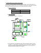
1. Load Door Switches
There are two (2) of these switches located under the main loading doors. These switches
Ensure that the doors are closed before the dryer can start. If the dryer is started when the
load doors are open, the microprocessor controller (computer) L.E.D. display will show “door”
2. Lint Basket Switch
This switch ensures that the lint basket is closed be before the dryer can start. This switch is
located at the front of the dryer at the right side of lint basket. If the lint basket is open when
the dryer is started, then the microprocessor controller (Computer) L.E.D. display will show
“door”
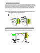
3. Basket (tumbler) Hi-Limit Safety Thermostat
This disc temperature switch has a setting of 225 F. It is located below the basket (tumbler)
on the temperature sensor bracket, along side the computer sensor, and is an automatic
reset type of switch. Access to this switch is gained by sliding/pulling the lint basket/drawer
completely out of the dryer.
This switch backs up the computer sensor and in case of a computer sensor malfunction will
prevent the basket’s (tumbler’s) temperature from becoming excessive. If this switch trips, the
gas flow to the burner box will be shut down; However, the basket (tumbler) will still rotate
4. Burner Box Hi-limit Safety Thermostat (GAS DRYERS ONLY)
This disc temperature switch has a setting of 330 F. It is located on the right side of the
burner
box, and is an automatic reset type of switch. This switch ensures that there is proper airflow
through the burner box. Upon a low airflow condition, which ensures may be caused by a
clogged lint screen, excessively long or blocked exhaust duct, or improper make-up air, the
temperature in the burner box will increase tripping this switch. This will shut off the gas flow
to the burner box; However, the basket (tumbler) will still run.
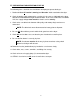
5. Sail Switch (GAS DRYERS ONLY)
The sail switch is located in the front top of the burner box. A sail switch consists of a round
damper plate on a lever arm which is in contact with an electric switch. When the air blower
comes on, it draws air through the gas burner. This creates a negative pressure inside the
burner box, and this negative pressure pulls in the round damper and activates the sail
switch. If there is an improper (low) airflow through the dryer, the sail switch damper will not
pull in, preventing the heat from
Low airflow through the dryer will be caused by overly long or blocked exhaust ducting, lack
of make-up air, or a clogged lint screen.
E. STEAM DAMPER ACTUATOR SYSTEM
This system consists of a hinged damper plate, pneumatic piston, and 24-volt solenoid valve
with a needle valve to control the speed of the piston actuation.