Ironer IP Series Installation and Operation Manual B&C Technologies Panama City, FL (850) 249-2222 (850) 249-2226 FAX www.bandctech.com Revision 1.1 09-June-2006 Accurate Technologies Samutprakarn, Thailand +66 (0) 2740-5511 +66 (0) 2740-5522 FAX www.accuratethai.
FOR YOUR SAFETY - CAUTION! WARNING: For your safety the information in this manual must be followed to minimize the risk of fire or explosion or to prevent property damage, personal injury or death. C C C Do not store or use gasoline or other flammable vapors and liquids in the vicinity of this or any other appliance. WHAT TO DO IF YOU SMELL GAS: ! Do not try to light any appliance ! Do not touch any electrical switch; do not use any phone in your building.
Table of Contents B&C Technologies Panama City, FL (850) 249-2222 (850) 249-2226 FAX www.bandctech.com Ordering Information Model Identification Key Symbols Safety Instructions Receiving Inspection General Specifications Electrical Connections Gas Connection Exhaust Requirements Steam Connections Initial Start Up Controls Operation Troubleshooting Periodic Maintenance 6 6 7 9 11 12 14 15 17 18 19 20 21 23 24 Accurate Technologies Samutprakarn, Thailand +66 (0) 2740-5511 +66 (0) 2740-5522 FAX www.
Ironer Parts Ordering Information If you require literature or spare parts, please contact your local distributor. If a local distributor is unavailable, you may contact B&C Technologies directly at (850) 249-2222 for the name of your nearest parts dealer. In Thailand: Phone: +66 (0) 2740-5511 FAX: +66 (0) 2740-5522 e-mail: sales@accuratethai.com Web: www.accuratethai.
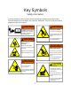
Key Symbols Safety Information Anyone operating or servicing this machine must follow the safety rules in this manual. Particular attention must be paid to the DANGER, WARNING, and CAUTION blocks which appear throughout the manual WARNING WARNING Moving parts hazard. To prevent serious injury or death, read machine manuals before installing, operating, serviceing, or cleaning machine. Can cause serious injury. Do not operate unless all guards and covers are in place.
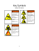
Key Symbols Safety Information WARNING WARNING To prevent serious injury or death: Burn and crush hazards. To avoid serious injury, keep hands/fingers, clothing, hair and jewelry away from all hot rolls and moving parts. Before removing jams, servicing, cleaning, or adjusting equipment, turn off all electrical power and other utilities. Before attempting to free jammed flatwork: Follow lockout/tagout procedures.
Important Instructions Safety Information Installation Notice: warning, For personal safety and for proper operation, the machine must be grounded in accordance with state and local codes and in the USA in accordance with the National Electric Code, article 250-96. Elsewhere, the equipment should be grounded in accordance with ANSI/NFPA 70, or the Canadian Electrical Code, CSA C22.1. The ground connection must be to a proven earth ground, not to conduit or water pipes. 4.
Important Instructions Safety Information 10. Do not install the machine in an area where it could be exposed to water or weather. 11. Do not alter or tamper with the control system. 12. To reduce the risk of fire, do not process plastics or articles containing foam rubber or similarly textured rubber-like materials. 13. Keep the area near the exhaust ducting clean and free of lint, dust, dirt or debris. 14. Keep the interior and exterior of the machine clean of lint, dirt, dust and debris.
Installation Receiving Inspection Upon receipt of the equipment, visually inspect for shipping damage and note any damage with the carrier before signing the shipping receipt, or advise the carrier of the damage as soon as it is noted. If damage is discovered, a written claim must be filed with the carrier as soon as possible.
Installation General Specifications and Utilitiy Connection Points Exhaust Outlet, 8”∅ A 1.77 'A' IP-1478 IP-1485 IP-14100 Electrical Connection Gas Inlet, ½” Steam Inlet, ¾” Steam Outlet, ½” 12 26.38 mm 2500 2680 3061 in 98.5 105.5 120.
Installation General Specifications IP-1478 Model Number of Rolls Roll Diameter Working Width Speed Range Dimensions Width Depth Height Canopy Height Exhaust System Air Flow Exhaust Duct Drive Information Drive Motor Blower Motor Steam Consumption Pressure Inlet Size Outlet Size Gas Heat Input Gas Inlet Size Electric Heat Heating Element Weight & Shipping Net Weight Shipping Weight IP-1485 IP-14100 Metric US mm mm m/min inch inch ft/min 355.6 2000 1.8-11 14 78 6-36 355.6 2159 1.
Installation Electrical Connection Electrical connections should be made by a qualified electrician in accordance with all applicable codes or requirements. Use a separate branch circuit to power each machine. Do not share circuits with lighting or any other equipment. in accordance with state and local codes and in the USA in accordance with the National Electric Code, article 250-96. The ground connection must be to a proven earth ground, not to conduit or water pipes.
Installation Gas Connection If local codes permit, use a new flexible stainless steel connector (Design certified by the American Gas Association or CSA International) to connect between the ironer and the gas supply line. Use an elbow and a ½” flare x ¾” NPT adapter fitting between the stainless steel gas connector and the gas inlet of the machine as needed to prevent kinking. Gas Supply Line !¾" IPS pipe is recommended. !¾” approved tubing is acceptable for lengths under 25 ft (6.
Installation Gas Connection After the reconfiguration is complete, the manifold pressure must be verified for proper operation. All instructions supplied with the regulator kit must be followed to ensure proper operation. Manifold Pressure Be sure to check the manifold pressure. Use a manometer to verify that the manifold pressure matches the information on the serial sticker and the type of gas being used.
Installation Exhaust Requirements WARNING Toxic and fire hazzards. Machine produces gases, fumes and lint which may be toxic or catch fire and could result in serious injury or death. Vent exhaust outdoors and regularly clean lint away from machine. For best results, install the ironer near an outside wall in order to keep the exhaust duct length as short as possible, and to provide a source of make-up air. Neither the rear nor the sides of the ironer should be blocked.
Installation Steam Connections Install a union and valve in the steam supply and return lines for ease of service. For best results, operate with a steam pressure of 90-125 psi (6.2-8.6 bar). The steam inlet and return are located on the right rear of the machine. The inlet is marked as such and is ¾” NPT (Female). The return is marked as such and is ½” NPT (Female). Install an inverted bucket trap with strainer and a check valve.
Installation Initial Start Up 9. Double check that the exhaust fan is rotating in the direction indicated on the blower housing. Additional information can be found on page 17. Before operating the ironer, check the following: 1. Check that the machine is level and in a stable position on the floor. The machine should not rock or move in any way. 10. Make sure the feeding belts are acting to pull linen into the machine (belts traveling towards the heated cylinder) 2.
Operation Controls 1 EMERGENCY STOP EMERGENCY STOP 2 1 TEMPERATURE CONTROL SLOW FAST on ADJUST SPEED 130 3 °C set 6 STOP START 4 JOG REV.
Operation Procedure Notice: Do not perform maintenance on this machine while it is running, the cylinder is hot, or while the machine’s circuit breaker is on. ironer when pressed. If the ironer does not stop, discontinue use and follow all lock out/tag out procedures and call a qualified service technician. Prior to starting the first shift of the day: 6. Restart the ironer by pressing the green start button for 1-2 seconds. 1. Inspect the area between the thermostat sled and the ironing cylinder.
Operation Procedure speed according to the weight and residual moisture of the goods. Obviously, thicker, wetter goods will require slower speeds than thinner, dryer goods. 11. Remove the finished goods from the output table, and fold or hang goods to prevent wrinkling. 12. To shut down the ironer at the end of the day, turn the heat switch to the OFF position, and allow the ironer to cool down to 70 °C (158 °F) before pressing the red stop button to power down the ironer. Proper feeding of small goods.
Basic Troubleshooting Procedure Temperature Control shows O-E Indicates an open circuit in the temperature probe wiring circuit - check cable connections at the temperature controller and the probe wiring for damage. Temperature Control shows S-E Indicates a short circuit in the temperature probe wiring circuit - check the probe cable for damage. Temperature Control shows Err Damaged sensor. Replace. Ironer will not start or stops suddenly -Make sure the Emergency Stop button isn’t pressed.
Periodic Maintenance Procedure Daily For steam models, inspect the rotary steam joint for leaks. If a leak is noted, a repair kit is available. Contact B&C Technologies for information. Inspect the temperature pick up sled and the cylinder. Remove debris if present. Make sure the temperature pick up sled is in full contact with the ironing cylinder. At shut down, wipe machine down with a mild cleaning agent and vacuum or sweep up any lint that has accumulated.