Dryer M720 Programming and Operation Manual August 9, 2013 Revision 1.
Contents 1 2 3 Important Safety Information 1 1.1 1 Control Overview 2 2.1 Features . . . . . . . . . . . . . . . . . . . . . . . . . . . . . . . . . . . . . . . . . . . . 2 2.2 Display and Keypad Functions . . . . . . . . . . . . . . . . . . . . . . . . . . . . . . . 3 Operation 10 3.1 Selecting a Drying Program . . . . . . . . . . . . . . . . . . . . . . . . . . . . . . . . . 10 3.1.1 Selecting an adjusted program . . . . . . . . . . . . . . . . . . . . . . . . . . . 10 3.1.
4.3 Delayed Start . . . . . . . . . . . . . . . . . . . . . . . . . . . . . . . . . . . . . . . . . 18 4.4 Counter Menu . . . . . . . . . . . . . . . . . . . . . . . . . . . . . . . . . . . . . . . . . 18 4.4.1 Counters per Program . . . . . . . . . . . . . . . . . . . . . . . . . . . . . . . . 19 4.4.2 Counters per Day . . . . . . . . . . . . . . . . . . . . . . . . . . . . . . . . . . . 19 4.4.3 Counters in Total . . . . . . . . . . . . . . . . . . . . . . . . . . . . . . . . . . . 20 4.4.
Chapter 1 Important Safety Information 1.1 FOR YOUR SAFETY - CAUTION! WARNING: For your safety the information in this manual must be followed to minimize the risk of fire or explosion or to prevent property damage, personal injury or death. • Do not store or use gasoline or other flammable vapors and liquids in the vicinity of this or any other appliance. • WHAT TO DO IF YOU SMELL GAS: – Do not try to light any appliance – Do not touch any electrical switch; do not use any phone in your building.
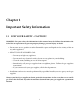
Chapter 2 Control Overview The M720 is a user configurable microprocessor controller used to control dryers. Because of the versatility of the software, it can be used in almost any type of dryer, without the need to modify the software. 2.1 Features The controller has the following features: • 192 x 32 pixels display. • 3 large 7-segment displays to indicate estimated time left and alarms. • 20 buttons with cap-sense technology.
• Power supply monitoring. • Full worldwide character set, including Chinese, Japanese, Thai, Russian, Arabic and Greek characters. • Stores up to 50 different languages. • No parameter settings will be lost in case of power supply failure or battery. • Self-configurable start-up logo, which can be used to customize the controller. • Edit and add languages with the use of free software. • Extended test programs which allow the user to monitor and control each input/output individually.
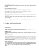
Figure 2.
A pre-defined drying program or a single cycle program can only be chosen if there is no active drying cycle, a cool-down cycle or when a program is finished but there is still a batch inside the machine. In practice this means that this key only works if the machine is in the ready to start state. 5. S TART key This key is used to (re)start the machine and to reset alarm messages. If an alarm is active, and the cause of the alarm has been solved, the alarm can be reset by pushing this key.
Pushing the E NTER key without the S HIFT key (see item 10) means enter or accept. If the key is pressed in combination with the S HIFT key (see item 10), is becomes the C LEAR function. The E NTER key is used to confirm a choice or an adjustment. For example, if another program is selected from the list, the E NTER key must be pressed to confirm the choice. This is the same when a parameter value is changed.
When a drying or cool-down cycle is active, the adjusted drying or cool-down time is set at the moment the drying or cool-down cycle starts. Sometimes it is necessary to manually adjust the time to a higher or lower value. This can be done with these buttons in combination with the S HIFT key (see item 10). If the S HIFT key (see item 10) is pressed in combination ), the current time remaining in the drying or with the INCREASE CYCLE TIME key ( cool-down cycle will be increased by 5 minutes.
Table 2.
Table 2.
Chapter 3 Operation The basic operation of the machine consists of the following steps: 1. Select a drying program 2. Starting the program 3. Program running 4. Program completed 3.1 Selecting a Drying Program Before a drying program is started, the user must make sure that the correct drying program is selected. The drying program is displayed in the upper line of the overview screen (see Chapter 4 on page 16).
In this screen, a predefined program can be selected with the numeric buttons 0 to 9 or with the A RROW U P and the A RROW D OWN buttons. The currently selected program number, together with the program name is displayed in the lower line of the display. If the arrow buttons are used in combination with the S HIFT key, the selected program will be increased or decreased by 10. When the correct program has been selected, confirm by pressing the E NTER key.
3.1.4 Program Operation In this phase the program cycle is running. A program cycle can be a drying step, a cool-down step or both. When running, the 2nd line in the overview screen will show the current status (see Chapter 4 on page 16). If an alarm occurs, the machine will be stopped by the controller and the program cycle will be paused. The same will happen if the S TOP key is pressed. When cause of the alarm has been corrected, the alarm can be reset with the S TART key.
on the lower display. If the machine is running, the lower line is used to display temperatures and time left to finish cycle. Before starting the machine, the overview screen may look like: 1 : Program name Ready to start The screen indicates that program number 1 is selected and that the machine is ready to start. If the S TART key is pressed, the software will check if all inputs are in the right state.
sensor or a humidity sensor, the text D RYING will be toggled with the current automatic drying value. Automatic drying means that the current drying method in the program parameters is set to A UTO. If so, the controller will continuously check if the current batch is dry. To determine this, it will use a second temperature sensor, an infra-red sensor or a humidity sensor, whichever one is available. 3.2.
and to notify the user that a program is finished and that the batch is ready to be taken out. If an alarm is active, the numeric display will toggle between - - - and the current alarm number. In this case the lower line of the graphical display will show the alarm text corresponding with the alarm number. For a full explanation of all available alarms, see Chapter 5 on page 39. If a drying or cool-down cycle is running, the numeric display will show the estimated time left for the cycle in minutes.
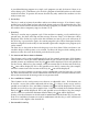
Chapter 4 Programming 4.1 Menu Structure If a parameter setting needs to be changed, a counter needs to be read or reset or test programs need to be run, these items can all be accessed via the main menu. The main menu can be accessed by pushing the set-up key in the main screen. The set-up key is the S HIFT key in combination with the H OME key. + Press the S HIFT and H OME key combination and the main menu will be displayed.
Figure 4.
Table 4.1: M720 Passwords Level Password Description 1 1234 Reset counters per program Edit program parameters Edit program name Test outputs manually 2 9999 Reset counters in total Edit machine parameters Change language Restore factory settings 3 1658 Edit machine configuration 4.3 Delayed Start With the M720 controller it is possible to define a delayed start. If this menu item is chosen, the screen for entering the start delay will be displayed.
drying program has its own counters. The second and third set are for a counter set per day (Counters Per Day) and counter set with totals of all programs and all days (Counters In Total). The fourth set is a non-resettable counter set, used to read counters processed since the controller was fabricated. 4.4.1 Counters per Program With the counter set Counters Per Program the user can read how many batches and how many operating minutes have been done in a certain program.
• Running minutes The number of minutes a program cycle has been active this day. It is not possible to reset the day counters. This is also not necessary since a new counter record will start from 0 automatically every day. To be able to use the counters per day information, it is important to ensure date and time are programmed correctly. See Section 4.7.1 on page 33. 4.4.
As the name suggests nonresettable counters cannot be reset. Also they are saved in EEPROM memory and not in battery backed-up memory. This means that, unlike the other 3 counter sets, these counters will not be lost when the battery fails or is removed. 4.5 Edit Parameter Menu The controller has 3 sets of parameters. There are parameters which can be programmed specifically for a drying program, so a program can be set-up to process a specific material. These are the program parameters.
Figure 4.
1. Drying method The standard controller is equipped with 1 temperature sensor – this parameter will not be available. If the machine is equipped with a second temperature sensor, a humidity sensor or with an infra-red sensor, this parameter will be available and can be set to T IME or to A UTO. If the parameter is set to T IME the program will do drying purely based on time, which means a drying step will always last exactly as long as the programmed drying time (see program parameter 6).
So, for example, if the temperature measured on the drum sensor (the standard temperature sensor) is 63o C and this parameter is set to 5o C, the batch is considered to be dry when the temperature measured by the infra-red sensor is higher than 58o C. 8. Humidity dry val. This parameter is available only when a humidity sensor is installed and the drying method (see parameter 1) is set to A UTO. This parameter is the humidity percentage to be detected in order to determine that the batch is dry.
14. Drum stop time If the machine is equipped with a reversing drum motor, and program parameter 13 is set to reversing, this parameter allows the time the drum will stop when switching direction to be defined. So, after running for the time defined in parameter 16, the drum will stop for the time defined in parameter 15 and then start again in the other direction. If no reversible drum is installed or the drum direction is not set to reverse, this parameter will not be available.
Changing the character where the cursor is on can be done with the numeric keypad, in more or less the same way text messages are created on cell-phones. See Table 4.2 on page 26 and Figure 4.3 on page 27 for details. Table 4.2: M720 Program Naming Key Functions key 1 2 3 4 5 6 7 8 9 0 4.5.3 Character Sequence ,.
Figure 4.
Figure 4.
1. Tmp in fahrenheit Set this parameter to Y ES if all temperature settings and displays should be displayed in Fahrenheit units instead of Celsius. If this parameter is N O, all temperature settings and displays will be displayed in Celsius units. Note: This value only changes the units used for displaying temperature values. Internally the controller always works with Fahrenheit units. 2. Maintenance cycle Use this parameter for setting the number of batches until a maintenance request is done.
Every controller in a network must be programmed to the same communication speed. In cases where long cables are used to connect controllers to the network, or in case of difficulties with communication between PC and controller, often a lower communication speed is necessary. When this parameter is changed, the controller must be restarted. 7. Cnt.reset no pass If this parameter is set to yes, the counters per program (see Section 4.4.1 on page 19) can be reset without a password.
13. Del. check airflow When a program is started the controller will check if the airflow switch (input 3) is in the off position. After that the blower will be started. After starting the blowers the airflow switch should go to the on position within a given period otherwise an alarm will be displayed. This parameter is the delay interval between the moment the blower starts and the moment the airflow switch should be in the on position. 4.
4.6.2 View Status of Outputs The View status of outputs screen can be used to check if the controller board is activating an output. Viewing the status of an output can be done while the machine is running. Selecting a module number and channel number is done in the same way as in the View status of inputs screen (see section 4.6.1 on page 31).
4.7 System Setup Menu The System set-up menu is a menu with items which are not directly related to the control functions of the machine itself but define the complete installation and user interface. The available items are used to set-up some extra features of the controller. 4.7.1 Adjust Date and Time Password level 1 is required to be able to adjust current date and current time.
4.7.3 Restore Factory Settings Restoring factory settings should normally not be necessary because all parameters are stored in non- volatile memory, which does not need a battery to retain its data. But, in some cases it can be useful to be able to go completely back to factory settings. If the item Restore factory settings is chosen from the System setup menu, and the password level is sufficient, the screen for restoring factory settings will be displayed.
4.8 Alarm History The alarm history list can be viewed by selecting Alarm history in the main menu. The alarm history is a list with the last 50 alarms, warnings and messages which have occurred. The alarm history is stored in the battery backed-up memory. In the alarm history screen the upper line displays which record number is currently displayed. Scrolling through the list of records is done with the A RROW U P and A RROW D OWN keys. The maximum number of items saved is 50.
to confirm change, followed by after all changes are made. The following configuration parameters are available: 1. Startup logo nr. When the controller starts up a start-up logo will be displayed for 5 seconds. Depending on manufacturer and distributor, it can be useful to change the start-up logo. If the value of this parameter is 0, no start-up logo will be displayed. 2. Humidity sensor This parameter indicates if a humidity sensor is present in the exhaust.
• Value 0: Output on when a drying cycle or cool-down cycle is busy. In this case the output will be switched on when a drying cycle starts and will switch off when the program is finished. This means that the output will always be on, even if the machine is stopped by an alarm or by the user, until a program is completed. • Value 1: Output on when a program is finished.
of the manual is being used as a reference. This information must also be provided with each support request.
Chapter 5 Alarms If the machine detects an alarm or a warning a message will be displayed on the 2nd line of the overview screen. In some cases, the numeric display above the graphical display will also blink with the alarm number. Alarms can be reset with the S TART key. Only one alarm is reset at a time so if multiple alarms are active the start key must be pressed once for each alarm. The alarms are the messages with number 1 to 24.
The input for the error of the frequency inverter (input 11) is configured to be a pulse train input. This means that the controller must detect a certain pattern on this input signal. If not, the machine is stopped out of safety issues because if this pulse train is not detected, a malfunction of this signal can be possible. • Control panel blocked In some circumstances, it is possible that the controller locks itself. If this happens, an unlocking code must be entered.
Also please note that if the lint filter door or drawer is opened when a program is running the air flow will change which can also cause the switch to open. In this case an additional air flow sensor error will be given. • Temperature sensor 1 error The cable of temperature sensor 1 is broken or there is a short circuit, or the sensor has failed. The controller detects that the sensor is not properly connected or is malfuntioning.
means it cannot determine if the batch is dry. The machine is still able to run if the humidity sensor is broken, but it cannot run on automatic drying any more. In order to run the machine, the sensor should be replaced or a program with time-based drying should be chosen. • Clean lint filter The dryer controller will monitor input 16 to check if the filter needs to be cleaned. If the controller detects that the filter needs to be cleaned this message will be displayed.
Chapter 6 Default Settings and Default Programs 6.1 Default Values Because the programmed language can vary, no default program names are set, except for program 100, which will be called Single cycle. Table 6.1: M720 Factory Default Values Parameter 1 3 4 5 7 8 9 10 18 19 23 24 25 26 29 32 33 Description Drying method Min. drying time Max. drying time Drying time Dry temperature Offset sensor 2 Offset infrared Humidity dry val. Cooldown time Cooldown temp.
Table 6.2: M720 Factory Default Programs Program Drying Time 1 40 2 30 3 30 4 40 5 25 6 25 7 25 8 20 9 0 10 50 50 20 Drying temperature 167 o F / 75 o C 140 o F / 60 o C 113 o F / 45 o C 140 o F / 60 o C 122 o F / 50 o C 113 o F / 45 o C 104 o F / 40 o C 104 o F / 40 o C n/a (only cool down) 194 o F / 90 o C 140 o F / 60 o C Table 6.3: M720 Factory Default Machine Parameters Parameter 1 5 6 7 11 12 16 26 27 30 31 32 33 40 Description Tmp in Fahrenheit Maintenance cycl Finished beeptim.
Chapter 7 M720 Input / Output Mapping Table 7.1: Connector J7 Pinout Pin 1 2 3 4 5 6 7 8 9 Point Input 1 Input 2 Input 3 Input 4 Input 5 Input 6 Input 7 Input 8 Common Function Door Lint Door Air Flow Overload N/C N/C Rotation Air Pressure? 0DC or Neutral Table 7.
Figure 7.1: M720 Connector Mapping Table 7.
Table 7.4: Connector J10 Pinout Pin 1 2 3 4 5 6 7 8 9 10 11 12 Point Output 1 Common Output 1 Output 2 Output 3 Output 4 Output 2,3,4,7,8 Common Output 5 Output 5,6 Common Output 6 Output 7 Output 8 NO Output 8 NC Function Cooldown Damper Status Heat Recirculation Damper Blower Wye/Delta FWD REV Blower Wye/Delta Heat Heat Table 7.