
User Manual

GT® FLOW CENTER
INSTALLATION INSTRUCTIONS
NOTE: Read the entire instruction manual before starting the installation.
WARRANTY
This flow center is warranted for five years from date of sale, excluding the 3-230KFC-SS, which is only a two year
warranty. Alleged defective product must be returned to B&D Mfg., Inc., 901 9th Street, Scranton, Iowa 51462, for
inspection via prepaid freight. Defective parts will be repaired or replaced at the manufacturer’s discretion. No allowance
for labor or property damage is implied. Warranty of performance is limited to the table provided with the unit and only
when being used in a closed-loop, heat pump system. No warranty of performance is provided when pump(s) are
provided by others.
INTRODUCTION
These instructions cover the installation of the GT
®
Flow Center Part No. 0(1)-NPFC-SS, 0(2)-NPFC-SS, 1-230PFC-SS, 2-
230PFC-SS and 3-230KFC-SS. The GT
®
Flow Center is a prepackaged pumping station to be used with closed-loop,
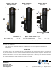
ground source heat pumps. The package contains a water vessel, an air-eliminating dip tube, a pump protecting check
valve, pump(s) and ball valves that allow the pump(s) to be removed for service without loss of fluid to the system.
SAFETY CONSIDERATIONS
Installing and servicing of air conditioning and heating equipment can be hazardous due to system pressures and
electrical components. Only trained, qualified personnel should install, start-up and service this equipment.
Untrained personnel can perform basic maintenance functions such as cleaning coils or cleaning and replacing filters. All
other operations should be performed by trained service personnel.
When working on the equipment, observe precautions in the literature, tags, stickers and labels attached to the
equipment and to any other safety precautions that apply.
Follow all safety codes. Wear safety glasses and work gloves.
B&D Mfg, Inc
901 9th Street
Scranton, IA 51462
Phone (712) 652-3424
Fax (712) 652-3388
www.bdmfginc.com
Patent No. 5,244,037
1
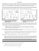
Fig. 1.
26-99 Pump Center Flow Chart
Fig. 2.
26-116 Pump Center Flow Chart
Fig. 3.
NRF36 Pump Center Flow Chart