
User Manual
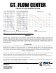
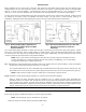

Fig. 4. Recommended Piping Schematic For
Maximum Flexibility (Required With
Internal Headers)
Fig. 5. Recommended Schematic (For Use with
Underground Headers; Flush Cart
Required)
INSTALLATION
Before installing the GT
®
Flow Center, check the flow charts and loop table against system flow and pressure drop
characteristics to be sure the correct flow center is selected for the system. A one-pump flow center can accommodate
flow for 3 1/2-ton units and smaller. A two-pump flow center can accommodate flow for 3 1/2- through 6-ton units.
(See Fig. 1, 2 & 3) To ensure adequate flow, the selection must be made based on your specific system design.
The flow center must be located between the heat pump and the ground source system heat exchanger. Location should
be selected on the basis of ease of installation and future service. The flow center is used for filling, flushing, air
elimination, adding anti-freeze and operating the system. This flow center should never be pressurized.
The recommended piping schematic is usable with all types of closed-loop, ground source heat pump systems, vertical
bore holes, horizontal loops, slinky, outside headers or inside headers. This recommended method allows for isolating
the heat pump or the loop field for separate flushing and purging. Additionally, the flow through the loops can be
reversed, which may be required when using external headers.
NOTE: The GT
®
Flow Centers are designed to work with only one heat pump per loop field. More than
one GT
®
Flow Center on a common loop field will not work properly. Call B&D Mfg., Inc. for information
on equipment designed for multiple heat pumps.
Fig. 4 Illustrates a recommended piping schematic that can be utilized when an internal header is used and separate
purging of the heat pump and the ground loop is not required.
It is recommended that a tee with a threaded plug is located between the heat pump and the ground loop. This
plug allows the air to be vented from the system piping and will help remove air from the system during start up.
NOTE: Loops should not contain any dirt or debris prior to connecting to the flow center.
Fig. 5 Illustrates a recommended piping schematic for a system with underground headers.
Piping is similar for either schematic with the exception of Fig. 4 showing all earth loops penetrating the
mechanical area of the interior wall. Provide ball valves and P/T ports where indicated. Ball valves shall be the
same as pipe size or greater. The flow center should be fastened to the wall with the bracket provided and all
piping should be adequately supported. All piping shall be properly sized for the flow rate (GPM) required by the
system. Reduce pipe size only at flow center and heat pump as necessary to make connections.
PROCEDURE 1—FILL AND FLUSH A NEW SYSTEM
On systems where the ground loop has been filled and flushed by the loop installer, skip to Procedure 3.
Ensure that all piping is installed according to one of the piping schematics.
NOTE: Incorrect piping may not eliminate the air pockets.
1. Open the top of the canister and fill with clean potable water.
2