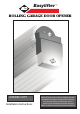
Easylifter ™ ROLLING GARAGE DOOR OPENER OWNERS COPY Installation Instructions Warning: It is vital for the safety of persons to follow all instructions. Failure to comply with the installation instructions and the safety warnings may result in serious personal injury and/or property and remote control opener damage. Please save these instructions for future reference.
IMPORTANT SAFETY INSTRUCTIONS Warning - It is vital for the safety of persons to follow all instructions. Failure to comply with the following Safety Rules may result in serious personal injury and/or property damage. For ADDITIONAL SAFETY protection we STRONGLY recommend the fitting of a Photo Electric Beam. In most countries Photo Electric Beams are mandatory on all garage doors fitted with automatic openers.
FEATURES Your Easylifter Auomatic Rolling Garage Door Opener has many features which you will appreciate. The components and materials used in this Automatic Opener are of the latest technology and highest quality. Listed below are some of the many features. SECURITY CODE STORE The Easylifter Garage Door Opener uses state of the art technology in storing your selected transmitter security code. Up to 8 transmitters can be stored in the openers memory.
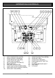
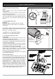
OPERATING CONTROLS 1. LIGHT CODE button (White) is used for storing or erasing the transmitter button (code) you wish to use to turn the opener’s courtesy light on and off. 7. O/S/C button (Yellow) is used during installation to test the Open, Stop and Close cycles for the Opener. The opener has to be initialised by the Reset button before the O/S/C button becomes operable. 2. DOOR CODE button (Blue) is used for storing or erasing the 8.
OPERATING CONTROLS 1) 2) 3) 4) 5) 6) 7) 8) 9) 10) 11) 12) 13) 14) 15) 16) 17) 18) LIGHT CODE BUTTON (WHITE) DOOR CODE BUTTON (BLUE) CLOSE DRIVE BUTTON (RED) CLOSE LIMIT LED (RED) AUTO CLOSE BUTTON (WHITE) RESET BUTTON O/S/C BUTTON (YELLOW) CLOSE LIMIT ADJUST SCREW (RED) OPEN LIMIT ADJUST SCREW (GREEN) OPEN LIMIT CAM (GREEN) 6 OPEN DRIVE BUTTON (GREEN) OPEN LIMIT (RED) CLOSE LIMIT CAM (RED) FORCE MARGIN SET BUTTON P.E. INPUT EXTERNAL RECEIVER INPUT O/S/C INPUT P.
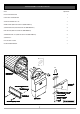
PACKAGE CONTENTS ITEM QUANTITY EASYLIFTER DRIVE UNIT 1 HAND HELD TRANSMITTER 1 ALKALINE BATTERY A23 12V 1 WEIGHT BARS (NOT INCLUDED IN SOME MODELS) 2 SCREW M5x40mm (NOT INCLUDED IN SOME MODELS) 4 HEX NUT M5 (NOT INCLUDED IN SOME MODELS) 4 SPRING WASHER I.
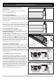
BEFORE INSTALLATION IMPORTANT SAFETY INSTRUCTIONS FOR INSTALLATION MINIMUM SIDE ROOM FIG. 1 RECOMMENDED SIDE ROOM FIG. 2 Warning: Incorrect installation can lead to severe injury. Follow ALL installation instructions. SIDE ROOM REQUIREMENTS Fig. 1 shows the minimum side room that is required. The distance between the edge of the door curtain and the inside of the bracket is 85mm minimum, and the distance between the edge of the door curtain and the outside of the bracket is 135mm minimum. Fig.
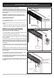
MOUNTING THE OPENER 4. FIXING DRIVE UNIT TO THE DOOR CHECK IF “U” BOLT IS TIGHT The Easylifter Drive Assembly can be fixed to the rolling garage door in a variety of ways. Described below is one method of fixing. Make sure there is enough side room (135mm from the end of the door shaft to the wall) to slide the drive unit onto the shaft. PLEASE NOTE: THE INSTRUCTIONS FOR FIXING THE DRIVE ASSEMBLY TO THE DOOR IS FOR RIGHT HAND INSTALLATION. FIG. 10 FITTING DRIVE UNIT TO DOOR (Fig. 10, Fig. 11 and Fig.
SETTING LIMITS 5. FIXING OF DOOR CURTAIN TO DRUM WHEEL The door curtain has to be secured to the drum wheel with suitable fasteners. 1. With the door in the fully closed position, mark the curtain (Fig. 13) on both ends of the door. 2. Open door slightly to have access to the marked positions. Secure the curtain to drum wheel using self drilling screws (two on each end). The screws should be at least 90 degrees apart (Fig. 13). FIG. 13 90 ° DRUM WHEEL 6.
SETTING LIMITS NOTE: If the door has not reached the desired limit position by more then 30mm, then it is recommended that the green limits cam be adjusted again before the green fine adjustment screw is adjusted. FIG. 16 CLOSE LIMIT ADJUSTMENT Press in and hold the red Close button .(Fig. 16). The door should start closing. Release the red Close button when the door reaches the desired closed position. If the red LED (Fig.
SETTING LIMITS OPEN LIMIT ADJUSTMENT Press and hold the green Open button (Fig. 18). The door should start opening. Release the Open button when the door reaches the desired open limit stop position. If the green LED (Fig. 18) is illuminated and the desired limit stop position has been reached then the limit adjustment is complete. If the green LED is illuminated but you are not happy with the door open position, the green Fine Adjustment Screw (Fig. 18) can be adjusted to fine tune the open position.
SETTING SAFETY OBSTRUCTION FORCE 7. SETTING OPEN AND CLOSE SAFETY OBSTRUCTION FORCE The Safety Obstruction Force is calculated automatically and set in memory on the Easylifter. This applies to both the Open Force and Close Force. FIG. 20 Warning: When step 7.1 is initiated the garage door will do a full open and close cycle automatically. Please keep doorway clear to avoid any personal injury or damage to property. 7.1 TO INITIALISE OBSTRUCTION FORCE 1. Press and hold the Close button (Fig.
CODING TRANSMITTERS 8. STORING TRANSMITTER CODES Make sure to connect the battery to the transmitters. The memory in the openers receiver can store up to remote control transmitters buttons. FIG. 22 PRESS AND HOLD DOOR CODE BUTTON 8.1 STORING TRANSMITTER CODE 1. Press the DOOR CODE button on the Easylifter opener. The Door Code LED will illuminate to indicate that learn mode is activated. If a valid code is not stored in 15 seconds the Easylifter opener will exit learn mode. 2.
CODING TRANSMITTERS 11. SETTING THE TRANSMITTER TO OPERATE THE COURTESY LIGHT FIG. 25 Although the courtesy light comes on with each operation of the opener, the courtesy light may also be controlled by a remote control transmitter without operating the door. To code one of the remote control transmitter buttons to turn the courtesy light on and off: 1 - Press the Light Code button on the opener.
PE BEAM AND AUTO CLOSE 14. FITTING THE SAFETY PHOTO FIG. 28 ELECTRIC BEAM SENSOR (OPTIONAL) Locate the Photo Electric Beam (P.E.) normally closed contact type in a strategic location within doorway. We recommend 150mm above the floor level and as close as possible to the door opening, inside the garage. Remove shunt from P.E connector (Fig. 28) and connect the plug from the P.E. wiring harness to P.E. connector (Fig. 29). The wiring diagram is for Model PHBE (Order Code 062153).
PARAMETERS & SPECIFICATIONS DOOR STATUS INDICATORS OPEN LED GREEN DOOR OPENER STATE OPEN CLOSE LED RED DOOR STATUS LED YELLOW BEEPER ON ON CLOSE FLASHING OPENING FLASHING CLOSING DOOR TRAVEL STOPPED FLASHING DOOR OBSTRUCTED WHEN OPENING FLASHING FLASHING DOOR OBSTRUCTED WHEN CLOSING FLASHING DOOR OVERLOADED ALTERNATING FLASHES DOOR IN OPEN POSITION WITH AUTO CLOSE MODE SELECTED ONE SECOND FLASHES MAINS POWER INTERRUPTED BEEPS WHILE DOOR IS MOVING ALTERNATING FLASHES RAPID FLASHES TEC
TROUBLE SHOOTING SYMPTOM POSSIBLE CAUSE Door will not operate. REMEDY Mains power not switched on. Switch on mains power. Door is obstructed. Remove obstruction. Door is locked or motor jammed. Unlock door or remove jam. Door tracks/hardware damaged. Door requires service/repair by qualified technician. Door starts to close but automatically reverses to open position.
SPARE PARTS LIST 19
WARRANTY 1. Definitions ‘B&D’ means (a) in Australia - B&D Doors of 17 Oasis Court, Clontarf, Queensland, 4019, a division of B&D Australia Pty Ltd (ABN 25 010 473 971), or (b) in New Zealand - B&D Doors NZ Ltd of 70 Allens Road East Tamaki Auckland, which is a subsidiary of B&D Australia Pty Ltd. ‘Purchaser’ means the purchaser of the Opener. ‘Opener’ means the ‘Easylifter Automatic Garage Door Opener’ ‘Authorised Distributor’ means an approved B&D distributor of the Opener.
WARRANTY 9. Subject to paragraph 12 hereof; (i) (ii) 10. the obligations of B&D under this warranty are limited to those contained herein and such warranties are expressly in lieu of all other warranties, express or implied, including any implied warranty of merchantability or fitness for a particular purpose and notwithstanding any course of dealing between the parties or custom and usage in the trade to the contrary.
QLD Office: 17 Oasis Court, Clontarf 4019. Ph: (07) 3883 0200 NSW Office: 34-36 Marigold St, Revesby 2212. Ph: (02) 9722 5555 VIC/TAS Office: 147-153 Canterbury Road, Kilsyth 3137. Ph: (03) 9237 7766 SA Office: 23 Frederick Road, Royal Park 5014. Ph: (08) 8440 4747 WA Office: 96 Mulgul Drive, Malaga 6090. Ph: (08) 9247 8777 NZ Office: 70 Allens Road, East Tamaki, Auckland. www.bnd.co.nz Ph: (09) 273 8600 B&D Doors is a Division of B&D Australia Pty Limited - ABN 25 010 473 971 www.bnd.