INSTRUCTIONS with 433MHz Radio Controls QLD Office: 17 Oasis Court Clontarf 4019 SA Office: (07) 3883-0200 NSW Office: 34-36 Marigold Street Revesby 2212 (02) 9722 5555 23 Frederick Road Royal Park 5014 (08) 8447 4747 WA Office: 96 Mulgul Road Malaga 6090 (08) 9247 8777 VIC/TAS Office: 147-153 Canterbury Road Kilsyth 3137 C-Tick approval logo min. size 3mm diam.; letters min. 3mm high (03) 9237 7766 B&D Doors New Zealand: 70 Allens Road EastTamaki Auckland, New Zealand (09) 273 8600 www.bnd.
TABLE OF CONTENTS Introduction Adjustment Section 2-7 Adjust the travel limits ...............................................25 Adjust the force .........................................................26 Test the safety reverse system .................................27 Testing the safety infra-red safety sensors ...............27 Safety rule review........................................................2 Preparing your garage door ........................................3 Tools needed ...............
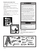
Preparing your garage door WARN ARNING ING • Disable locks. Insert wood screws or nails to keep them unlocked. • Remove any ropes connected to garage door. To prevent possible SERIOUS INJURY OR DEATH: • Always call for professional B&D garage door service if garage door binds, sticks, or is out of balance. An unbalanced garage door might not reverse when required.
Planning • Do you have an access door in addition to the garage door? If not, Model T7012 Emergency Access Device is required. Identify the type and height of your garage door. Survey your garage area to see if any of the conditions below apply to your installation. Additional materials may be required. You may find it helpful to refer back to this page and the accompanying illustrations as you proceed with the installation of your opener.
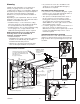
OFF CENTRE INSTALLATION OF OPENER In situations where obstruction prevent mounting the opener centrally, offsetting the opener attachment is possible within the following range - 1/4 Door width from centre. NOTE: Even though it is acceptable practise to off centre mount the opener, the further off centre the opener is mounted the more dependent is the door operation on a good installation. This relates to correct set-up of opener and track, and correct door balance.
Carton Inventory Hardware for assembly and installation is shown on the next page. Save the carton and packing material until installation and adjustment is complete. Your garage door opener is packaged in two cartons which contains the motor unit and the parts illustrated below. If anything is missing, carefully check the packing material. Parts may be stuck in the foam.
Hardware Inventory Separate all hardware and group as shown below for the assembly and installation procedures.
HARDWARE SHOWN ACTUAL SIZE ASSEMBLY STEP 1 Assemble the Rail NOTE: If your opener came with a one piece rail, proceed to Assembly step 2, page 9. Grease inside edges of rail brace sections. Place rail pieces on flat surface for assembly. All four rail sections are interchangeable. Slide rail braces onto rail section. Connect rail by sliding rail brace onto next rail section. Tap rail assembly on piece of wood until rail sections are flush. Repeat with remaining rail sections.
ASSEMBLY STEP 2 Attach Trolley to Rail Slide outer trolley into rail assembly, be sure arrow on trolley is heading in direction of door is heading in direction of door. Slide outer trolley down rail until it engages with inner trolley. Arrow Rail Assembly WARN ARNING ING Outer Trolley Arrow CAUTION To avoid serious damage to opener, ONLY use screws mounted in top of motor unit.
FASTEN RAIL TO OPENER SET CHAIN TENSION Spreader Stops HARDWARE SHOWN ACTUAL SIZE Spring /Trolley Nut Washered Bolt Stops Spreader Sprocket Sprocket Nut Ring Screwdriver Tip Wrench Bolt 2 4 Trolley Stop Bolt Hole Spring Nut Lock Washer Nut Header Sleeve Lock Washer Bolt Trolley Square End Square End Nut Ring BEFORE 25mm Nut Trolley Nut Ring AFTER RELEASE 32mm Screwdriver Tip ASSEMBLY STEP 5 Nut Ring Install Chain Noise Reduction Pads (optional) Wrench 114mm Spring Nut 114mm He
INSTALLATION NING WARN ARNING INGINSTRUCTIONS IMPORTANT INSTALLATION ION WARN ARNING ING To reduce the risk of severe injury or death: 1. READ AND FOLLOW ALL INSTALLATION WARNINGS AND INSTRUCTIONS. 2. Install garage door opener only on properly balanced and lubricated garage door. An improperly balanced door may not reverse when required and could result in severe injury or death. 3.
INSTALLATION STEP 1 Finished Ceiling Vertical Centreline Determine the Header Bracket Location 40mm Reinforcement Board Structural Supports Header Wall Installation procedures vary according to garage door types. Follow the instructions which apply to your door.
One Piece Door Without Track 1/30/92 - 4/7/92 ONE-PIECE DOOR WITHOUT TRACK Unfinished 1. Close the door and mark the inside vertical Ceiling 40mm centreline of your garage door. Extend the line Reinforcement onto the header wall above door, as shown. Board Header Vertical Wall If headroom clearance is minimal, you can install Centreline the header bracket on the ceiling. See page 14. If you need to install the header bracket on a 40mm reinforcement board (on wall or ceiling), Theuse Chamberlain Group, Inc.
INSTALLATION STEP 2 Install the Header Bracket Bracket Holes WALL HEADER BRACKET INSTALLATION Wall Mounting Holes • Centre the bracket on the vertical guideline with the bottom edge CEILING of the bracket on the horizontal line MOUNT ONLY The nail hole is for (with the arrow pointing towardpositioning the ceiling). only. You must use lag screws UP • Mark all of the bracket holes. Drill 4.5mm (3/16") to mount the header bracket. pilot holes and fasten the bracket with wood screws.
INSTALLATION STEP 3 Attach the Rail to the Header Bracket • Position opener on garage floor below the header bracket. Use packing material to protect the cover. Raise rail until holes in the header sleeve and holes in the header bracket align. Join with clevis pins. Insert ring fasteners to secure. NOTE: To enable the rail to clear sectional door springs, it may be necessary to lift opener onto a temporary support. The opener must either be secured to a support or held firmly in place by another person.
Rail Door 25mm Board laid flat Door ONE-PIECE DOOR WITHOUT TRACK • With the door fully open and parallel to the floor, measure the distance from the floor to the top of the door. • Using a stepladder as a support, raise the top of the opener to this height. • The top of the door should be level with the top of the motor unit. Do not position the opener more than 50mm above this point.
INSTALLATION STEP 6 Lighted Door Control Button Terminal Screws Install the door control Bell Wire WHT -2 Locate the door control within sight of the door at a minimum height of 1.5m where small children cannot reach, and away from all moving parts of the door and door hardware. 1. Strip 6mm of insulation from one end of the bell wire. Connect it to the two screw terminals on the back of the door control by color: white wire to 2 and white/red wire to 1. 2.
WARN ARNING ING WARNING WIRING INSTRUCTIONS FOR ACCESSORIES To prevent possible SERIOUS INJURY or DEATH from electrocution: • Be sure power is not connected BEFORE installing door control. To prevent possible SERIOUS INJURY or DEATH from a closing garage door: • Install door control within sight of garage door, out of reach of children at a minimum height of 1.5m, and away from all moving parts of door.
WARN ARNING ING INSTALLATION STEP 8 Attach the Emergency Release Rope and Handle • To prevent possible SERIOUS INJURY or DEATH from a falling garage door: – If possible, use emergency release handle to disengage trolley ONLY when garage door is CLOSED. Weak or broken springs or unbalanced door could result in an open door falling rapidly and/or unexpectedly. – NEVER use emergency release handle unless garage doorway is clear of persons and obstructions. • NEVER use handle to pull door open or closed.
The units must be installed inside the garage so that the sending and receiving eyes face each other across the door, between 100-150mm above the floor. Either can be installed on the left or right of the door as long as the sun never shines directly into the receiving eye lens. The brackets must be securely fastened to a solid surface such as the wall framing. If installing in masonry construction, add a piece of wood at each location to avoid drilling extra holes in masonry if repositioning is necessary.
WARN ARNING ING CAUTION INSTALLATION STEP 11 Fasten the Door Bracket Fibreglass, aluminum or lightweight steel garage doors WILL REQUIRE reinforcement BEFORE installation of door bracket. To prevent damage to garage doors reinforce inside of door with angle iron both vertically and horizontally. Follow instructions which apply to your door type as illustrated below or on the following page. A horizontal reinforcement brace should be long enough to be secured to two or three vertical supports.
ONE-PIECE DOORS Please read and comply with the warnings and reinforcement instructions on the previous page. They apply to one-piece doors also. • Centre the door bracket on the top of the door, in line with the header bracket as shown. Mark either the left and right, or the top and bottom holes. • Metal Doors: Drill 4.5mm (3/16") pilot holes and fasten the bracket with the 8 x 13mm (1/4"14x5/8") self-threading screws provided.
INSTALLATION STEP 12 Inner Trolley Connect Door Arm to Trolley Outer Trolley Follow instructions which apply to your door type as illustrated below and on the following page. SECTIONAL DOORS ONLY • Make sure garage door is fully closed. Pull the emergency release handle to disconnect the outer trolley from the inner trolley. Slide the outer trolley back (away from the door) about 200mm as shown in Figures 1, 2 and 3.
ALL ONE-PIECE DOORS Door Bracket Assemble the Door Arm: • Fasten the straight and curved door arm sections together to the longest possible length (with a 2 or 3 hole overlap). • With the door closed, connect the straight door arm section to the door bracket with the 8mm x 32mm clevis pin. • Secure with a ring fastener. Ring Fastener Lock Washers 8mm Clevis Pin 8mm x 32mm Nuts 8mm Straight Arm Screws 8mm x 20mm Curved Door Arm • Press the Remote Control transmitter button.
WARN ARNING ING ADJUSTMENT STEP 1 Limit Adjustment Without a properly installed safety reversal system, persons (particularly small children) could be SERIOUSLY INJURED or KILLED by a closing garage door. • Incorrect adjustment of garage door travel limits will interfere with proper operation of safety reversal system. • If one control (force or travel limits) is adjusted, the other control may also need adjustment. • After ANY adjustments are made, the safety reversal system MUST be tested.
ADJUSTMENT STEP 2 WARN ARNING ING Adjust the Force The force, as measured on the closing edge of the door, should not exceed 400N (40kg). If the closing force is measured to more than 400N, a Safety Infrared Reversing Sensor must be installed See step 3 on page 27. The force setting button is located on the back panel of the motor unit. The force setting regulates the- SEARS Adjust Force amount of power required to open and close the door.
Step 3 Test Safety Reverse System SEARS 315-699 (Yellow Disk #2) Models 53315, 53415, 535156, 53625 & 53699 ADJUSTMENT STEP 3 WARN ARNING ING 6/20/89 - 6/27/89 Test the Safety Reverse System Without a properly installed safety reversal system, persons (particularly small children) could be SERIOUSLY INJURED or KILLED by a closing garage door. • Safety reversal system MUST be tested every month. • If one control (force or travel limits) is adjusted, the other control may also need adjustment.
OPERATION NING WARN ARNING ING IMPORTANT SAFETY INSTRUCTIONS WARN ARNING ING To reduce the risk of severe injury or death: TION ION 1. READ AND FOLLOW ALL WARNINGS AND INSTRUCTIONS. 2. ALWAYS keep remote controls out of reach of children. NEVER permit children to operate or play with garage door control push buttons or remote controls. 3. ONLY activate garage door when it can be seen clearly, it is properly adjusted, and there are no obstructions to door travel. 4.
To Open the Door Manually Care of Your Opener LIMIT AND FORCE ADJUSTMENTS: Weather conditions may Limit Controls cause some minor changes in door operation requiring some re-adjustments, particularly during the first year of Adjustment Label operation. (Located on the left side panel) Pages 25 and 26 refer to the limit and force adjustments. Force Controls Repeat the safety reverse test (Adjustment Step 3, page 27) after any adjustment of limits or force.
Troubleshooting 1. Opener doesn't operate from either door control or remote: • Does the opener have electric power? Plug lamp into outlet. If it doesn't light, check the fuse box or the circuit breaker. (Some outlets are controlled by a wall switch.) • Have you disengaged all door locks? Review installation instruction warnings on page 1. • Is there a build-up of ice or snow under door? The door may be frozen to ground. Remove any obstruction. • The garage door spring may be broken. Have it replaced.
9 1 7 9 3 1 7 5 3 5 KG KG PROGRAMMING SPECIFICATIONS Below are instructions for programming your opener to operate with remote control transmitters. Horsepower ....................1/2 Rated Pull Force.............800N Stand-by power rating @ 230V...........................5.5W 9 9 1 7 3 5 USING THE “SMART” BUTTON 9 1 7 9 3 1. Press and hold the button on the hand-held remote* that you wish to operate your garage door. L ift M 3 5 2.
WARRANTY Controll-A-Door® Automatic Garage Door Opener 1. Definitions ‘B&D’ means (a) in Australia - B&D Doors of 17 Oasis Court Clontarf, Queensland 4019 (b) in New Zealand - B&D Doors (NZ) Ltd of 70 Allens Road East Tamaki Auckland, which is a subsidiary of Alesco NZ Ltd. ‘Purchaser’ means the purchaser of the Opener. ‘Opener’ means the ‘Controll-A-Door Automatic Garage Door Opener’ ‘Approved Distributor’ means an approved B&D distributor of the Opener.