H5000 Installation Manual ENGLISH www.bandg.
Preface As Navico is continuously improving this product, we retain the right to make changes to the product at any time which may not be reflected in this version of the manual. Please contact your nearest distributor if you require any further assistance. It is the owner’s sole responsibility to install and use the instrument and transducers in a manner that will not cause accidents, personal injury or property damage. The user of this product is solely responsible for observing safe boating practices.
Declarations and conformance This equipment is intended for use in international waters as coastal sea area administered by countries of the E.U. and E.E.A. The H5000 system complies with the following regulations: • CE under EMC directive 2004/108/EC • Level 2 devices of the Radio communications (Electromagnetic Compatibility) standard 2008 • The relevant Declaration of conformity is available in the H5000 section on the following website: www.bandg.
Liability and safety warning Navico accept no responsibility for the use and/or operation of this equipment. It is the user’s responsibility to ensure that under all circumstances the equipment is used for the purposes for which it has been designed. Warning: Calibration The safe operation of this equipment is dependent on accurate and correct calibration. Incorrect calibration of this equipment may lead to false and inaccurate navigational readings placing the yacht into danger.
Contents 7 7 7 Introduction About B&G About this manual 8 9 10 11 System introduction H5000 system example H5000 performance system example H5000 typical autopilot system 12 Planning 12 Mounting locations 14 14 15 16 17 18 System architecture NMEA 2000® device connection Wiring guidelines Network layout Bridged network Network power supply 19 20 21 25 26 26 26 27 27 27 28 28 29 29 29 30 30 H5000 Central Processor Unit - CPU Status LEDs CPU Installation H5000 Central Processor wiring Power supply Mast
37 External sensor wiring Analog Expansion 37 Masthead unit 37 5 V Analog input / 0 V to +5 V signal 38 Paddle wheel 39 Paddle wheel & Sea temperature 40 External sensor wiring Serial Expansion 40 NMEA 0183 - GPS Antenna 40 Halcyon Gyro Stabilized Compass - HGSC 41 Sensor Modules 42 42 42 42 43 43 44 44 45 45 45 46 46 47 Autopilot H5000 Pilot Computer General Wiring Power Drive Engage (Clutch) Alarm NMEA 0183 Rudder Remote Simnet (Network) Turning on for the first time H5000 Pilot Controller 49 Commission
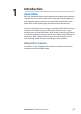
1 Introduction About B&G B&G has welcomed the constant challenge to develop new electronic solutions for every sailor’s need. Harnessing technical developments and providing proven solutions has continued to be the focus that keeps B&G on the leading edge of advanced marine electronics.
2 System introduction The innovative B&G H5000 instrument system is powered by a smart Central Processing Unit (CPU) with the ability to run three levels of software, Hydra, Hercules and Performance. H5000 is designed for all sailing types from cruising to racing and provides the sophistication you need without over-complication.
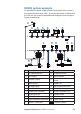
H5000 system example An example of a typical H5000 system. At the centre of the system is the Central Processor Unit (CPU). All sensor information is fed back to the CPU and can be easily controlled and configured via the Graphic Display or webserver. 1 2 4 3 5 6 7 12V T 12V 8 9 10 12 11 T 14 16 15 PILOT 12V 17 12V 13 18 WIFI-1 12V 19 No. Description 20 No.
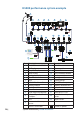
H5000 performance system example 1 2 4 3 5 6 7 8 PLOT MARK GO TO VESSEL MENU WIN IN OUT 1MOB 2 ABC 4 GHI 5 JKL 7 PQRS 8 TUV STBY AUTO CHART 12V RADAR ECHO NAV INFO 0 3 DEF 6 MNO 9WXYZ PWR PAGES 12V T 12V 9 10 15 16 17 13 11 9 14 12 T 18 19 22 26 12V 27 No.
H5000 typical autopilot system 2 1 3 4 5 T T 12V 6 8 9 12V 11 12V 10 DPT 7 No. Description No.
3 Planning Mounting locations H5000 CPU The H5000 CPU should be installed in a dry place with easy accessibility. The enclosure is water resistant to IP65 but will not survive prolonged immersion. The engine box is NOT a good place to install your instrument system processors; it is hot and electrically noisy. The H5000 CPU does not contain orientation sensitive components so it is NOT necessary to mount the unit vertically, however it is recommended to orientate the unit with all cable exits downwards.
General Ensure that any holes cut are in a safe position and will not weaken the boat’s structure. If in doubt, consult a qualified boat builder. Before cutting a hole in a panel, make sure that there are no hidden electrical wires or other parts behind the panel. Do not mount any part where it can be used as a hand hold, where it might be submerged, or where it will interfere with the operation, launching or retrieving of the boat. Leave sufficient clearance space to connect all relevant cables.
4 System architecture NMEA 2000® device connection All devices connect to the network via a Micro-C connector. Essential network information • The network consists of a linear “backbone” from which “drop cables” connect to H5000 and NMEA 2000 devices • H5000 products use Micro-C style connectors, this allows compatibility with NMEA 2000 networks. Note: Some B&G products use Simnet proprietary connectors, but are compatible via adaptor cables. • A single drop cable has a maximum length of 6 m (20 ft).
Wiring guidelines The network cabling should be such that the network cable run is predominantly in a linear layout with a start point and end point (which are terminated). “Star” shaped layouts are inefficient, may cause incorrect operation and should be avoided. Note: H5000 uses Micro-C network cabling compatible with NMEA 2000 devices. Don’t do this...
Network layout Guideline maximum drop cable length For best performance it is recommended that drop cables (x) are kept short. However in some cases it may be necessary to utilise longer drops, in this case they should not exceed 6 meters. Note: The maximum cable length of the Micro-C network backbone is 100 meters. For larger systems a network bridge should be considered or use Mini-C cable for the network backbone which would allow a maximum of 200 meters.
Bridged network For networks that exceed the recommended network cabling maximum length a bridged network adaptor can be used. Note: When using a network bridge it is important that both networks are powered and terminated as per H5000 network guidelines. 3 1 2 T T T 12V T 12V PILOT 12V No. 1 2 T Description Micro-C CAN bus backbone 1 Micro-C CAN bus backbone 2 Micro-C Terminator No.
Network power supply The H5000 network requires its own 12 V DC power supply protected by a 5 amp fuse or breaker. For 24 V systems, use a DC-DC converter to supply 12 V Connect power at any location along the backbone for smaller systems. For larger systems introduce power at central point in the backbone to balance the voltage drop of the network.
5 H5000 Central Processor Unit - CPU 4 5 6 2 1 3 No. Description No.
Status LEDs On the top of the CPU there are 4 diagnostic / status LEDs.
CPU Installation 1: Find a suitable location to position the CPU. 2: Mount the CPU vertically. Ensure that there is at least 100 mm clearance between the cable grommet and any surface to enable easy access to cables. 3: Mark the hole positions, drill pilot holes and fix into position with four self tapping screws. 4: To remove the lid, unscrew the 6 captive lid screws anticlockwise. Note: The lid comes away from the CPU. The 6 captive screws remain fixed to the lid.
Note: Do not attach the terminal plug until the cable has been fed through the cable grommet! Ensure the grommet is orientated in the correct direction! 8: Wire the terminal plug as per the wiring instructions 9: Press the cable grommet back into place ensuring there is sufficient cable for the plug to reach the correct terminal.
10: Replace the grommet retaining clip. 11: Example of a basic CPU wired unit shown below.
12: Before replacing the lid ensure that the grommet and retaining clip are fitted correctly. The lid will then clamp everything in place. Tighten the 6 captive lid screws clockwise.
H5000 Central Processor wiring POWER NETWORK 5 2 1 3 USB ETHERNET 7 4 9 6 10 12 11 8 Connector layout No. 1 2 3 Analog - Inputs 3 & 4 9 4 5 Analog - Inputs 1 & 2 Pulse input Man Overboard and Alarm 10 11 Description NMEA 0183 - Channel 2 NMEA 0183 - Channel 1 Network (NMEA 2000 compatible) USB port Reset button 12 Ethernet (Webserver) 6 Description Power - 12 Volts Masthead unit No. 7 8 Note: There is a connection diagram on the inside of the processor lid.
Power supply 1 2 3 1 2 3 Color Red Black - Description 12 Volts 0 Volts Screen 1 2 3 4 5 6 7 8 Color Black Orange Red Green Blue Violet - Description 0 Volts 12 Volts Wind angle phase Wind angle phase Wind angle phase Wind speed Screen (if present) Color Sensor Dependent Sensor Dependent Sensor Dependent Sensor Dependent Sensor Dependent - Description Masthead Unit 1 2 3 4 5 6 7 8 Analog input 3 & 4 1 1 2 3 4 5 6 2 3 4 5 6 26 | 0 Volts 12 Volts 5 Volts 0 - 5 Volts (Analog 4) 0 - 5 Volts (Ana
Analog input 1 & 2 1 1 2 3 4 5 6 2 3 4 5 6 Color Sensor Dependent Sensor Dependent Sensor Dependent Sensor Dependent Sensor Dependent - Description 0 Volts 12 Volts 5 Volts 0 - 5 Volts (Analog 2) 0 - 5 Volts (Analog 1) Screen Pulse (Paddlewheel - Speed) 1 2 3 4 1 2 3 4 Color Black Red Green - Description 0 Volts 5 Volts Pulse Screen Man Overboard Button input 1 2 3 4 1 2 3 4 Color Black Red - Description Send Return - H5000 Central Processor Unit - CPU | H5000 Installation | 27
Digital output (Alarm) 1 2 3 4 Color Sensor Dependent Sensor Dependent 1 2 3 4 + 12 Volts Description Output 0 Volts 1 2 3 4 0 Volts NMEA 0183 - Channel 2 1 1 2 3 4 2 3 4 28 | Color Sensor Dependent Sensor Dependent Sensor Dependent Sensor Dependent Description TX_A ( - ) TX_B (+) RX_A ( - ) RX_B (+) H5000 Central Processor Unit - CPU | H5000 Installation
NMEA 0183 - Channel 1 1 1 2 3 4 2 3 4 Color Sensor Dependent Sensor Dependent Sensor Dependent Sensor Dependent Description TX_A ( - ) TX_B (+) RX_A ( - ) RX_B (+) Network (NMEA 2000 compatible) 1 2 3 4 1 2 3 4 Color Red Black White Blue Description 12 Volts 0 Volts Data high +ve Data low -ve USB update port The USB port is used for software upgrades only. For further information follow the software upgrade procedure in the maintenance section of this manual.
Reset button • Single press of the reset button whilst the system is powered up will initiate a reboot and soft reset of the CPU without cycling the power. • A long press of the reset button whilst powering up the CPU will initiate a full factory reset. Note: Performing a factory reset will revert all CPU settings to their default factory settings. Ethernet port Ethernet port. Direct connection to a computer or WiFi router.
Webserver Connections Direct via Ethernet Connect a computer directly to the CPU via an ethernet cable. Wireless via a WiFi-1 router Connect wireless devices to the CPU via a WiFi-1 WIFI-1 12V Note: To connect the WiFi-1 router to the H5000 CPU an Ethernet to RJ45 converter cable is required.
Accessing the webserver An up to date web browser that supports web sockets must be used to access the B&G H5000 Webserver. Via Ethernet 1 Connect device to the CPU (as shown previously). 2 Open web browser on the connected computer or device. 3 Type the IP address [ 192.168.0.2 ] into the web browser address bar Note: Unit will attempt to select a DHCP server for 2 minutes after power on. If the server is not detected the unit will revert to IP address [ 192.168.0.
6 Expansion Modules 1: Find a suitable location for the module. Mount the module vertically. Ensure that there is at least 100 mm clearance between the connector and grommet and any surface to enable easy access to cables 2: Mark the hole positions, drill pilot holes and fix into position with two self tapping screws 3: To remove the lid, unscrew the 4: Cut the grommet indicated to a length that creates a tight fit two lid screws. for the cable to be fed.
H5000 Expansion Module wiring The Analog and Serial Expansion Module connector terminals have differing functions. Below is a list of the connectors their terminal numbers and their functions. Note: The functions of individual ports on the Expansion Modules are set via the webserver interface.
H5000 Expansion Module wiring example Below is an example of how to wire an Analog module with a masthead unit and paddle wheel sensor.
Module Jumpers If a sensor or combination of sensors connected to an analog or Serial Expansion Module draw more than 300 mA current total, then a terminal link must be placed onto both jumpers located above the network connector, inside the module as shown below. This bypasses the isolated power supply within the module.
7 External sensor wiring Analog Expansion Masthead unit 8 7 6 5 4 3 2 1 1 2 3 4 5 6 7 8 Color Orange Black Blue Green Red Violet Input Screen 12 Volts 0 Volts Wind Angle Phase Wind Angle Phase Wind Angle Phase Wind Speed 5 V Analog input / 0 V to +5 V signal 1 2 3 4 5 8 7 6 5 4 3 2 1 6 7 8 CONNECTOR A (TOP TERMINALS) Color Input Channel Screen Black 0 Volts Red 5 Volts Sensor Signal Analog 1 dependent 0 V to +5 V Sensor Signal Analog 2 dependent 0 V to +5 V Sensor Signal Analog 3 dependent 0 V to +
1 2 3 4 5 8 7 6 5 4 3 2 1 6 7 8 CONNECTOR B (BOTTOM TERMINALS) Color Input Channel Screen Black 0 Volts Red 5 Volts Sensor Signal Analog 4 dependent 0 V to +5 V Sensor Signal Analog 5 dependent 0 V to +5 V Sensor Signal Analog 6 dependent 0 V to +5 V - Note: 0 Volt to 5 Volt sensors can be wired into either Connector A or Connector B. If you plug a 0 - 5 Volt analog input into connector 1 then the analog channels will be 1, 2 & 3, if connected to connector 2 then they will be channels 4, 5 & 6.
Paddle wheel & Sea temperature 8 7 6 5 4 3 2 1 1 2 3 4 5 6 7 8 Color Black Red & White Yellow Green Input Screen 0 Volts 5 Volts Sea Temperature Speed Note: 10 K ohm resistor required between terminal 5 and 3 External sensor wiringAnalog Expansion | H5000 Installation | 39
8 External sensor wiring Serial Expansion NMEA 0183 - GPS Antenna 8 7 6 5 4 3 2 1 1 2 3 4 5 6 7 8 Color Red Black Sensor Dependent Sensor Dependent Sensor Dependent Sensor Dependent Input Screen 12 Volts 0 Volts TX_A (+) TX_B ( - ) RX_A (+) RX_B ( - ) Note: A link wire may be required (as shown) between terminals 3 & 6 and 6 & 8 depending on the sensor.
9 Sensor Modules There are three types of Sensor Module, Barometer, 3D Motion Sensor and Network Alarm. 1: Find a suitable location for the module. Mount the module vertically.
10 Autopilot H5000 Pilot Computer General The H5000 Pilot Computer is mounted as per the CPU instructions. Note: When the autopilot installation is completed, the system must be configured and the commissioning procedures performed. Failure in setting up the autopilot correctly may prohibit the autopilot from functioning properly. Wiring Access the terminals by removing the 6 captive screws in the H5000 Pilot Computer lid. Follow the same method as described for the CPU.
Power 1 Direct 1 2 2 Color Red Black Description 12 or 24 Volts 0 Volts Note: The power cable is hard wired directly to the supply terminal on the PCB. Drive 1 2 3 Direct Color 1 Drive Dependant 2 Drive Dependant 3 Drive Dependant Description Motor / Solenoid 1 Motor / Solenoid 2 Solenoid ground Note: The drive cable is hard wired directly to the drive terminal on the PCB. Reversing drive Hydraulic drives and rotary drives need connection to the Engage terminal for clutch operation.
Solenoid valves, 12 V or 24 V DC Solenoid Valve SOL GND MOTOR SOL-2 DRIVE SOL-1 SOL-1 SOL GND MOTOR SOL-1 H5000 Pilot Note: For solenoids with higher voltage (110/220 V AC or DC), use external relays/solid state relays.
NMEA 0183 1 2 1 2 3 4 3 4 Color Sensor Dependent Sensor Dependent Sensor Dependent Sensor Dependent Description Color Brown Grey Description Frequency + Frequency - Color Remote Dependant Remote Dependant Remote Dependant Remote Dependant Description RX_B RX_A TX_B TX_A Rudder 1 2 1 2 Remote 1 2 1 2 3 4 3 4 Autopilot | H5000 Installation Lamp Starboard Port Ground | 45
Simnet (Network) 1 2 3 4 1 2 3 4 Color Red Black White Blue Description 12 Volts 0 Volts Data high +ve Data low -ve Turning on for the first time Before attempting to turn on the autopilot and perform an installation setup, the hardware installation and electrical installation must be completed and in accordance with the installation instructions. The first time the autopilot system is started and after a factory reset, you will need to follow the setup and commissioning procedures as described.
H5000 Pilot Controller 1 4 2 5 3 6 7 8 Keys The H5000 Pilot Controller is operated by 8 keys. These are used to operate the autopilot and adjust autopilot parameters. 1 MODE Change the autopilot mode / Scrolls up in menu options / Increases values. With active autopilot: Toggles between Wind mode and Auto mode. Press and hold for further functions.
Connectors The H5000 Pilot Controller is equipped with 1 Micro-C flying lead.. Network The H5000 Pilot Controller can be connected at any point on the network. Note: The H5000 Pilot Controller is only compatible with the B&G H5000 Pilot.
11 Commissioning If an H5000 Pilot Computer and H5000 Pilot Controller are connected to the network then autopilot control and setup functionality can be accessed via the H5000 Pilot Controller. Warning: The installation settings must be performed as part of the commissioning of the autopilot system. Failure to do so correctly may prohibit the autopilot from functioning properly! The Installation menu can only be accessed in Standby mode.
Rudder calibration Make sure the Rudder Feedback unit is installed and aligned as per your Rudder Feedback installation manual. The rudder feedback calibration will set the correct relationship between the physical rudder movement and the rudder angle readout. Max starboard The Max starboard angle is the angle read by the rudder feedback unit before any adjustment is made. 1 Manually move the helm to starboard until the rudder stops at starboard lock hard over. Press 1º Starboard key to confirm.
Set Rudder mid point Bring the rudder to midship position and press 1º Starboard key to confirm. This will adjust any incorrect reading caused by misalignment of the rudder feedback unit. Rudder drive settings Ensure that the rudder information is set correctly before you continue with the Dockside commissioning. Drive voltage (V) Sets the drive voltage to the type installed on the vessel, 12 or 24 V. Drive engage Drive engage has the following settings: Auto and Clutch.
Rudder deadband The rudder deadband function is adaptive and is continuously updating. It prevents the rudder from hunting and the adaptive function optimizes the deadband to the speed of the boat and the load on the rudder. If the auto-setting does not perform properly due to high inertia from the wheel, it can be adjusted manually. Find the lowest possible value that will prevent the rudder from continuous hunting. A wide deadband will cause inaccurate steering.
Autotune Warning: Autotune must always be performed in open waters at a safe distance from other traffic. The Automatic tuning function may take from 2 to 3 minutes to complete. To stop the Autotune at any time, press the STBY key. Autotune is a feature that automatically sets the most important steering parameters (Rudder and Counter Rudder) by taking the boat through a number of S-turns.
Once complete the screen will display the word finished and there should be no need for further adjustments. Fine tuning of these parameters are made by the response control, however, viewing or changing the parameters can be made in Auto mode by entering Installation in the Main menu. Rudder gain Sets the rudder gain which is the ratio between the commanded angle and the heading error.
on the proportional rudder response caused by the heading error. It may sometimes appear as if it tends to make the rudder move to the wrong side (counter rudder). The best way of checking the value of the Counter Rudder setting is when making turns. The figures illustrate the effects of various Counter Rudder settings.
Sea trial After completing the autopilot calibration and all settings in the installation menu, you will need to perform a final sea trial. Note: The sea trial should be conducted in open waters at a safe distance from other traffic.
12 Maintenance General maintenance The instruments are not user repairable and the operator is therefore required to perform only a very limited amount of preventive maintenance. If the unit requires any form of cleaning, use fresh water and a mild soap solution (not a detergent). It is important to avoid using chemical cleaners, alcohols and hydrocarbons such as diesel, petrol etc. Always put on the weather cover when the unit is not in use.
Software upgrade H5000 CPU To upgrade the CPU software to the latest version, save the .upd file (upgrade file) to a USB memory stick. (Must be FAT or FAT32 format, NTFS is not supported) 1 Save .upd file to a USB Stick. (Must be in the root folder and not a subfolder) 2 Turn off power to the CPU 3 Remove the CPU lid 4 Insert USB stick into the USB port 5 Turn on power to the CPU 6 The CPU will automatically recognise the .
H5000 Pilot Computer / Pilot Controller To upgrade the H5000 Pilot Computer or controller to the latest software version, use the Navico Software Upgrade Tool. Follow the Navico SWUP (Software Upgrade) tool or an MFD. Graphic Display To upgrade the Graphic Display software to the latest version save the .upd file (upgrade file) to a USB memory stick. (Must be FAT or FAT32 format, NTFS is not supported) 1 Save .
Race display To upgrade the Race display to the latest software version use a MFD or Navico Software Upgrade Tool. Analog / Serial expansion module To upgrade Analog / Serial expansion modules to the latest software version use a MFD or the Navico Software Upgrade Tool. Navico NMEA 2000 devices To upgrade NMEA 2000 devices to the latest software version use a MFD or the Navico Software Upgrade Tool.
H5000 Central Processor Unit - CPU 196.0 mm (7.72") 92.0 mm (7.68") 211.0 mm (8.31") 195.0 mm (7.68") 65.5 mm (2.58") 13 Technical drawings & specifications Weight Supply voltage Power consumption Can bus power consumption Color Environmental Protection Safe distance to compass 0.7 kg, 1.6 lbs 12 V DC Nominal (9-16 V) 2.4 Watts (200 mA @ 12 V) Typical 0.6 Watts (50 mA @ 12 V) Typical (NMEA 2000® equivalent 1 LEN) Black IPX4 0.3 m (1.0 ft.
Graphic Display 32.0 mm (1.26") 10.0 mm (0.39") 114.0 mm (4.49") Product Outline Sun Cover Outline 119.0 mm (4.69") Product Outline 178.0 mm (7.01") 184.5 mm (7.26") Sun Cover Outline Weight Supply voltage Power consumption Color Display Size Type Color Resolution Environmental Protection Safe distance to compass 62 | 0.45 kg (1.0 lbs) 12 V DC Nominal (9-16 V) Network powered 1.9 Watts (160 mA @ 12 V) Typical 2.3 Watts (190 mA @ 12 V) Max.
Race display 32.0 mm (1.26") 10.0 mm (0.39") 114.0 mm (4.49") Product Outline Sun Cover Outline 119.0 mm (4.69") Product Outline 178.0 mm (7.01") 184.5 mm (7.26") Sun Cover Outline Weight Supply voltage Power consumption Color Display Size Type Color Resolution Environmental Protection Safe distance to compass 0.45 kg (1 lbs) 12 V DC Nominal (9-16 V) Network powered 0.6 Watt (50 mA @ 12 V) Typical 1.0 Watts (86 mA @ 12 V) Max.
H5000 Pilot Computer 65.5 mm (2.58") 196.0 mm (7.72") 92.0 mm (7.68") 211.0 mm (8.31") 195.0 mm (7.68") Weight Supply voltage Power consumption Color Environmental Protection Safe distance to compass 64 | 0.7 kg, 1.6 lbs 12 V DC Nominal (9-16 V) 0.6 Watts (50 mA @ 12 V) Typical (NMEA 2000® equivalent 1 LEN) Black IPX4 0.3 m (1.0 ft.
H5000 Pilot Controller 32.0 mm (1.26") 9.0 mm (0.35") 114 mm (4.49") Sun Cover Outline 119 mm (4.69") Product Outline 70.0 mm (2.76") 76.5 mm (3.01") Sun Cover Outline Weight Power consumption Color Display Size Type Color Resolution Environmental Protection Safe distance to compass 0.18 kg (0.4 lbs) 1.2 Watt (100 mA @ 12 V) Typical 1.6 Watts (130 mA @ 12 V) Max. (NMEA 2000® equivalent 3 LEN) Black 2” (Diagonal) LED / Transflective Monochrome 128 x 64 pixels IPX7 0.3 m (1.0 ft.
www.bandg.