
User guide


14 |
System architecture | H5000 Installation
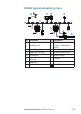
System architecture
NMEA 2000® device connection
All devices connect to the network via a Micro-C connector.
Essential network information
• The network consists of a linear “backbone” from which “drop cables”
connect to H5000 and NMEA 2000 devices
• H5000 products use Micro-C style connectors, this allows
compatibility with NMEA 2000 networks.
Note: Some B&G products use Simnet proprietary connectors, but are
compatible via adaptor cables.
• A single drop cable has a maximum length of 6 m (20 ft). The total
length of all drop cables combined should not exceed 78 m (256 ft)
• The network has a maximum cable length of 100 m (328 ft), between
any two terminators
• The network needs to have a Micro-C Terminator at each end of the
backbone. A Micro-C Terminator can be one of the following:
• A Micro-C Terminator blank plug
• A 508 model wind transducer (where the mast cable is one end of
the backbone)
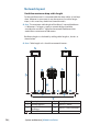
Planning and installing a network backbone
The network backbone needs to run between the locations of all
products you want to install, typically in a bow to stern layout, and be
no further than 6 m from a device to be connected.
Choose from the following components to make up your network
backbone:
• Micro-C interconnecting cables
• Micro-C power cables - with or without termination
• T-connectors. Use at locations where you want to connect a device by
drop cable
Note: If using a 508 wind sensor connected directly to the network,
the mast cable should be connected as the nal length of cable at
one end of the backbone, as the sensor is tted with a termination
resistor.
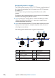
Note Most NMEA 2000 devices can be connected directly to the
network backbone. Simnet devices can be connected to the Micro-C
CAN bus backbone by using adapter cables.
4