
User guide


38 |
External sensor wiringAnalog Expansion | H5000 Installation
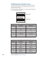
CONNECTOR B
(BOTTOM TERMINALS)
12345678
Color Input Channel
1 - Screen -
2 ---
3 Black 0 Volts -
4 Red 5 Volts -
5
Sensor
dependent
Signal
0 V to +5 V
Analog 4
6
Sensor
dependent
Signal
0 V to +5 V
Analog 5
7
Sensor
dependent
Signal
0 V to +5 V
Analog 6
8 ---
Note: 0 Volt to 5 Volt sensors can be wired into either Connector A
or Connector B. If you plug a 0 - 5 Volt analog input into connector 1
then the analog channels will be 1, 2 & 3, if connected to connector 2
then they will be channels 4, 5 & 6.
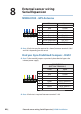
Paddle wheel
12345678
Color Input
1 - Screen
2 --
3 Black 0 Volts
4 Red 5 Volts
5 --
6 --
7 --
8 Green Speed