
User guide


42 |
Autopilot | H5000 Installation
Autopilot
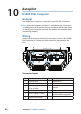
H5000 Pilot Computer
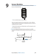
General
The H5000 Pilot Computer is mounted as per the CPU instructions.
Note: When the autopilot installation is completed, the system must
be con gured and the commissioning procedures performed. Failure
in setting up the autopilot correctly may prohibit the autopilot from
functioning properly.
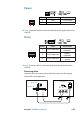
Wiring
Access the terminals by removing the 6 captive screws in the H5000
Pilot Computer lid. Follow the same method as described for the
CPU.
2
3
4
7
DRIVE
30 A FUSE
POLARITY LEDS
DRIVE
ENGAGE
SUPPLY
NMEA0183
ALARM
SCREEN
TERMINATION
REMOTE
SIMNET
RUDDER
5
6
8 9
10
11
1
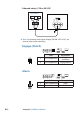
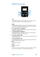
Connector layout
No. Description No. Description
1 Polarity LEDs 7 NMEA 0183
2 30 Amp fuse 8 Alarm
3
Power supply
12 or 24 Volts
9 Rudder
4 Drive output 10 Remote
5 Drive Engage - Clutch 11
Network
(NMEA 2000 compatible)
6 Screen Termination
10