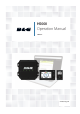
H5000 Operation Manual ENGLISH www.bandg.
Preface As Navico is continuously improving this product, we retain the right to make changes to the product at any time which may not be reflected in this version of the manual. Please contact your nearest distributor if you require any further assistance. It is the owner’s sole responsibility to install and use the instrument and transducers in a manner that will not cause accidents, personal injury or property damage. The user of this product is solely responsible for observing safe boating practices.
Contents 5 Introduction 5 About this manual 7 System overview 7 8 8 8 9 9 10 10 11 11 12 H5000 components H5000 Central Processor Unit - CPU Webserver - Network portal Graphic display Race display HV Displays Analog displays Expansion modules Sensor modules Alarm module H5000 Pilot Controller 13 System examples 13 14 15 16 16 Hydra Hercules Performance Autopilot minimum system requirement Basic System - No H5000 CPU 17 Operation 17 18 25 25 26 27 28 30 31 32 34 34 34 35 40 43 44 45 Graphic di
57 System setup 57 59 60 60 60 61 61 61 62 62 62 64 67 68 69 71 Network Units Language Time Simulate Restore defaults Global reset About Autopilot setup Source selection Rudder drive Commissioning Response Sailing Steering Setup 73 Webserver 78 Operating variables 105 Example data tables 105 106 106 106 106 Polar table Boat speed / Heel correction table True wind angle correction table True Wind Speed correction table Down wind speed correction table 107 Maintenance 107 108 4| Basic maintenance
1 Introduction About this manual This manual is a reference guide for operating the B&G H5000 instrument system. It assumes that all equipment is installed correctly, and that the system is ready to use. The manual assumes that the user has basic knowledge of navigation, nautical terminology and practices. The manual does not cover basic background information about how equipment such as radars, echo sounders and AIS work.
| Introduction | H5000 Operation Manual
System overview 2 The H5000 instrument and autopilot systems combine unique sailing features with raceproven technology in a straightforward package. Developed for blue water cruisers and racing yachts alike, the range brings powerful system options to match your exacting requirements.
H5000 Central Processor Unit - CPU The H5000 CPU takes sensor inputs and uses a dedicated processor to calculate and calibrate the data and distribute it to display units and external devices. Connect a router via the ethernet port to take advantage of the webserver interface via a PC, tablet or smart-phone. There is a USB port to upgrade the CPU with the latest software. Webserver - Network portal The browser-based configuration of the H5000 system enables advanced calibration, set-up and diagnostics.
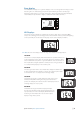
Race display The H5000 Race Display is a 7 segment display, 5-inch screen designed for viewing essential data at a glance. A dedicated page key allows quick switching between stored pages displaying 2 data values on each page alongside a unique bargraph providing immediate visual indication of performance targets, countdown timer status and more. MENU HV Displays The HVision range of displays are lightweight, single-line data units incorporating B&G’s unique HV technology.
Analog displays Before a value will be shown on an analog display ensure that a sensor (source) has been selected via the CPU or Graphic Display. Go to source selection to achieve this. The analog display backlighting is achieved by a long press of the MENU key on any of the Graphic displays. There is a wide range of analog indicators available, all listed below. • Apparent Wind Angle • Apparent Wind Speed • Boat Speed 12.
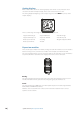
Sensor modules There are two types of H5000 sensor module. Barometric & temperature sensor Measures the atmospheric pressure and air temperature, allowing the CPU to record atmospheric pressure changes over varying periods of time and current air temperature. 3D Motion The Tri-Axis Motion Sensor provides accurate measurement of the heel and trim angles as well as pitch, roll and yaw rates of the yacht, allowing the CPU software to correct the wind data for errors induced by this motion.
H5000 Pilot Controller The H5000 Pilot Controller manages all autopilot functions as well as setup and commissioning. Use the H5000 Pilot Controller to select autopilot modes or manually steer the vessel.
Hydra An example of a typical H5000 system. At the centre of the system is the H5000 Central Processor Unit (CPU). All sensor information is fed back to the CPU and can be easily controlled and configured via the Graphic display. 1 2 4 3 5 6 7 12V T 12V 8 9 10 11 12 T 14 16 15 PILOT 12V 17 12V 13 18 WIFI-1 3 System examples 12V 19 No. Description 20 No.
Hercules 1 2 3 4 5 6 7 12V 8 12V T 12V 9 13 11 14 15 16 12 10 T 17 18 19 22 20 21 12V 12V 24 No. NMEA0183 Tx/Rx Description No.
Performance 1 2 4 3 5 6 7 8 PLOT MARK GO TO VESSEL MENU WIN IN OUT 1MOB 2 ABC 4 GHI 5 JKL 7 PQRS 8 TUV STBY AUTO CHART 12V RADAR ECHO NAV INFO 0 3 DEF 6 MNO 9WXYZ PWR PAGES 12V T 12V 9 10 15 16 17 13 11 9 14 12 T 18 19 22 26 12V 27 No. 23 21 20 20 28 Description 29 No.
Autopilot minimum system requirement 2 1 3 4 T T 12V 5 7 8 12V 10 12V 9 DPT 6 No. Description No. Description 1 Masthead unit 6 Speed sensor 2 Graphic display 7 H5000 Pilot Computer 3 H5000 Pilot Controller 8 Rudder Reference Unit 4 GPS antenna 9 Hydraulic Ram 5 H5000 Central Processor Unit 10 Compass T Terminator 12V 12 Volt DC power supply Basic System - No H5000 CPU 1 2 3 4 T T 12V 5 No. Description No.
Operation 4 Graphic display 1 2 3 4 MENU 5 Basic operation The first display added to the network will go into a startup wizard when it is first powered on. The startup wizard will need to be completed before the display can be used. Using the wizard, set the desired language, time, units and network source selection. 1 PAGE Each short press of the PAGE key scrolls through the data pages.
Standby MENU All of the displays can be placed in Standby mode via any display Setup dialog. ¼ Note: Once in Standby mode a single press of the MENU key will turn the displays back on. 3sec Default graphic display pages Sail Steer 7 1 8 2 3 9 4 10 5 11 6 Displayed data No. Description No.
Target wind angle There are 3 sources available for target wind angle. Polar Takes the target wind angle from your polar table Actual Takes the current value of target wind angle Manual Manually input the upwind and downwind numbers into the dialog boxes. Layline limits When selected will show a dotted line indicating the minimum and maximum tack/gybe time period either side of the layline. This can be set from 5 to 30 minutes in 5 minute increments. Speed / Depth 1 2 3 Displayed data No.
Wind plot 3 1 4 2 5 6 Displayed data No. Description No. Description 1 True wind direction 4 Mean value 2 True wind direction histogram 5 True Wind Speed histogram 3 True Wind Speed 6 Time period (5 to 60 minutes) ¼ Note: Wind histogram time periods can be set to show 1, 5, 10, 30 or a 60 minute history. Toggle between the time periods using the UP/DOWN keys. Start line 6 1 7 2 8 3 9 4 10 5 11 Displayed data No. 20 | Description No.
Setting up a Start line page The Start Line page is used as a visual aid to boat distance from the start line, tide direction, recommended start end bias and what advantage in degrees and boat lengths the biased end will give. ¼ Note: Before setting the start line position It is important that the Bow offset is updated to negate the difference between the GPS postion and the bow of the vessel. 1 Approach the port end of the start line 2 Select ping from the start Line menu 3 Highlight Port end...
Start line screen explained 1 4 5 2 3 6 Start line end not pinged (position not recorded) Start line end pinged (position recorded) Start line end stale (historic start line position) Start line end becomes stale at 23:59 hrs on the day it was recorded but remains valid.
Depth history 1 2 4 3 5 Displayed data No. Description No. Description 1 Current depth 4 Water line 2 Shallow water limit 5 Depth histogram 3 Depth scale ¼ Note: Depth histogram time periods can be set to show 5, 10, 30 or a 60 minute history. Toggle between the time periods using the UP/DOWN keys. Highway 6 1 7 2 8 3 9 4 10 5 11 Displayed data No. Description No.
Tide 6 1 7 2 3 8 4 9 5 10 Displayed data No. Description No. Description 1 Boat speed 6 TWA Port / Starboard indicator 2 Tide angle relative to vessel 7 True Wind Angle 3 Heading 8 True Wind Speed 4 Depth 9 True wind direction 5 Tide rate 10 Tide direction Autopilot 1 2 6 3 7 4 8 5 9 Displayed data No. 24 | Description No.
Data page transition 1 2 8 3 7 4 6 5 Available data pages 1 Sail steer (default) Full screen* 2 Speed / Depth 2x1 grid (default) 2x1 grid* 3 Wind plot (default) 2x2 grid* 4 Start line (default) 2x2 grid offset* 5 Depth history (default) 3x3 grid* 6 Highway (default) 1+3 digital* 7 Tide (default) 1+6 digital* 8 Autopilot (default) Centre analog* Satellites Analog +2* Weather Analog +3* Single time plot* Dual analog* Dual time plot* ¼ Note: * indicates, User configurable page
Replacing a data page 1 Go to the pages menu. 2 Highlight the page you wish to replace MENU x2 3 Press MENU 4 Highlight Replace and press the ENTER key 5 Highlight the desired page and press the ENTER key The new chosen page will be shown in the pages list. Enabling / Disabling a data page To make a data page available via the PAGE key you will need to first ensure it has been selected as one of the eight available pages.
Menus From a data page a single press of the MENU key will open the Page menu for that specific page. A double press of the MENU key will open up the Settings menu. MENU Page menu The Page menu options vary from page to page. All Page menus have a race timer and settings option to access the Settings menu. All other options listed will relate directly to the current data page. Settings menu The Settings menu is where display options, display and system settings and calibration can be accessed.
Race timer The race timer can be used to countdown to zero from a specified time, ideal for counting down to a race start. It can also be used to count up from zero to record the elapsed time. The timer can be started at any time by selecting Start Timer from the timer setup menu. If the start value is set to zero (00:00) when the timer is started the timer will begin counting up, recording the elapsed time. MENU x2 ¼ Note: The timer is shared between all displays on the network.
Start/Stop timer To start the timer, select Start in the Race Timer menu. When the timer is started it will return to the previous data page. To stop the timer from counting select Stop in the Race Timer menu. Sync When the timer is counting down selecting Sync will synchronize the time up or down to the nearest full minute. Reset Selecting Reset will reset the timer to the start value. If the timer was running, it will continue to run from the start value.
Man Over Board If an emergency situation should occur and a man over board event is triggered, the display automatically switches to the MOB screen. 1 4 5 2 6 3 7 Displayed data No. • • • Description No. Description 1 Last known MOB position 5 Direction to MOB from vessel 2 Bearing to MOB 6 Dead reckoned MOB position 3 Range to MOB 7 Last known MOB position 4 Vessel (Always points up) A waypoint becomes active at the position the man over board is activated.
HV display support Any compatible B&G HV display e.g. 20/20 HV mast display connected to the network can be configured via the H5000 CPU webserver, Graphic Display or Race Display to show desired data e.g. speed, depth, wind speed. ¼ Note: When a new HV display is added to the network the default data displayed will be boat speed. If no boat speed data source is available the display will show the word ‘OFF’ Remote displays The remote display page can be accessed from the Settings menu.
Alarms If you have the relevant sensor connected to the network you can enable that alarm by selecting it/them from the alarm list. Alarm on / off Turn an alarm on or off from the alarm list. A tick symbol next to the alarm in the alarm list will indicate that the alarm is on. ¼ Note: It is possible to enable / disable all alarms by selecting the ‘Alarms Enabled’ field from the Alarms menu.
Alarm indication The alarm system is activated if any alarm settings are exceeded. Alarms are indicated with an alarm text and with an audible alarm (optional). ¼ Note: See Alarm settings for further details on how to set an alarm. If an autopilot is not on the network, autopilot alarms will not be accessible. If no specific alarm text is available, an alarm code will appear. Acknowledging an alarm An alarm is acknowledged by pressing the ENTER key.
Damping The damping rate affects the frequency that the sensor data is updated, the greater the damping value the smoother the number change will be but the slower the response will be to data change. Damped parameters • • • • • • • • • Below is a list of parameters that a damping value can be applied to. Set the damping value (response rate) for each parameter from 0 to 9 seconds.
Race display 1 2 3 4 MENU 5 Basic operation 1 PAGE Each press of the PAGE key scrolls through the data pages in rotation or navigates back to the display pages from within any menu. Press and hold the PAGE key to save the current page configuration. 2 UP Selects the upper half of the display to change variables; scrolls through menus and variables; increases / decreases values. 3 ENTER Used to enter the selected sub menus and confirm selections.
Menus To enter the menu function press the MENU key. To operate a menu use the UP and DOWN directional keys and press the ENTER key to select a menu item. Press the PAGE key to navigate back to the display pages. Pages The display shows five configurable data pages. Data pages show a variety of data and information available from sensors and devices on the network. ¼ Note: All of the default pages can be edited to show the users preferred boat data.
Bargraph data editing Select Bargraph menu option, use the arrow keys to select the required bargraph variable. Press the PAGE key to save the change and return to the data page screen. MENU x7 Race timer The race timer can be used to countdown to zero from a specified time, ideal for counting down to a race start. It can also be used to count up from zero to record the elapsed time. ¼ Note: Once the countdown timer reaches zero it will start counting up showing the elapsed time from zero.
Stop Stops the timer. Press the ENTER key again to restart the timer. Reset If the timer is running, selecting reset will automatically start counting down from the originally set value for the race timer. If the timer is stopped when reset is selected it will set the clock to the originally set value and will not begin the countdown until start is selected. Remote displays Remote displays can be individually set via the race display to show a single variable.
Backlighting Set the desired lighting level on the display. ¼ Note: All units in the selected lighting zone will mirror each others light settings. Default setting is network. To change the lighting zone select the lighting menu and press DOWN the lighting zone type will flash. Select the desired zone and press the ENTER key. MENU Trip log There are two recorded trip logs. Trip log 1 records distance traveled through the water, trip log 2 records distance traveled via GPS input.
Alarm notification When an alarm event is received the display will change to show the variable name that is alarming and the current value. An icon will be highlighted to indicate the severity of the alarm. Alarm icons There are three alarm icons for the three levels of alarm severity as shown below. Important / Critical Warning Information Depth alarm example Acknowledging an alarm An alarm is acknowledged by pressing the ENTER key twice in quick succession.
Checksum Additional version information in hexadecimal format. This information is for B&G support only. 1 2 No. 1 Description Boot code No. 2 Description User code Full reset Factory reset of the display. All settings will revert to factory default. Select the full reset page, press the ENTER key and a full reset will take place and return the display back to the default speed and depth page. User reset Resets page configuration to their default settings. All other settings will remain unchanged.
Lights test Select the lights page. Press the ENTER key, the display will go through each of the light settings in sequence. It is the responsibility of the user to visually check the light levels. Instance The display instance is a number that can be set as a reference for the user to distinguish between different displays. By default the display instance is set to zero. Voltage Shows the current voltage supply to the display.
H5000 Pilot Controller a d b e f c 1 4 2 5 3 6 7 8 Display The displayed information will change depending which mode is selected. X Description X Description a Performance level d Target b Autopilot mode e Compass: ºT = True ºM = Magnetic c Rudder angle indicator f Heading Keys The H5000 Pilot Controller is operated by 8 keys. These are used to operate the autopilot and adjust autopilot parameters.
Autopilot operation Turning the autopilot on / off Engaging the autopilot At anytime while the autopilot is disengaged press the AUTO key to engage the autopilot. The autopilot will steer the boat on the current selected heading. Disengaging the autopilot At any time the autopilot is engaged press the STBY key to disengage the autopilot. The autopilot will go into Standby mode and you will be required to take manual control of the helm.
Autopilot modes The current heading and Set heading information will change on the display depending on which mode the autopilot is in. Below is a list of the autopilot modes, autopilot mode symbol and the current/target data that will be displayed.
Mode selection From Standby mode, press the AUTO key once to enter Auto mode. Whilst in Auto mode a single press of the MODE key will set the autopilot to Wind mode. Press the MODE key again to revert to Auto mode. To access other autopilot modes press and hold the MODE key for 2 seconds. Highlight the required mode and press the 1º RIGHT key to confirm. ¼ Note: The mode selection menu will time out after a few seconds. Whichever mode is highlighted at this time will be selected.
Tacking & Gybing in Wind mode Tacking & Gybing in Wind mode can be performed when sailing with apparent or true wind as the reference; in either case the True Wind Angle must be less than 90 degrees (tacking) and more than 120º (gybing). The tacking/gybing operation will mirror the set wind angle on the opposite tack and a tack confirmation window will appear on the display. To tack or gybe in wind mode press both 1° COURSE CONTROL keys on the H5000 Pilot Controller simultaneously.
Sensor calibration 5 Once the display is setup and before you proceed with calibration ensure all network sources are selected and configured as shown in section 6. Calibration example: Depth A typical transducer installation is through the hull in front of the keel. A datum (offset value) can be set, such that the depth display refers to either the water line or the base of the keel. +VE: Positive Datum for Waterline (0.
Setting a calibration value 1 2 3 4 Highlight the value field. Press the MENU key to enable editing of the calibration value. The cursor will flash in the value field. Use the UP/DOWN Keys to adjust the value or toggle between plus and minus (+ / -). Press the ENTER key to move to the next number in sequence. The current number will flash when selected. 5 Press the ENTER key when the last digit is highlighted in the calibration field to exit. 6 Select OK. 7 Press ENTER to confirm and exit.
Auto - Calibration via reference to GPS SOG value This is an AutoCal facility that uses speed over ground (SOG) from your GPS and compares the average of SOG against the average boat speed from the speed sensor for the duration of the calibration run. ¼ Note: This calibration should be made in calm sea with no effect from wind or tidal current.
Distance reference This facility enables the user to calibrate the log accurately and simply. Calculations are performed by the display that works out the boat speed over a known distance. To calibrate the boat speed via a distance reference you will need to complete consecutive runs, under power at a constant speed made along a given course and distance. ¼ Note: To eliminate the effect of tidal conditions it is advisable to perform at least two runs, preferably three, along the measured course.
Use SOG as boat speed If boat speed is not available from a paddle wheel sensor it is possible to use speed over ground from a GPS. SOG will be used in the true wind calculations. Environment Sea / Air Temperature & Barometric pressure If a suitable sensor is fitted, the system will monitor the current sea / air temperature and barometric pressure. The offset value to be entered should adjust the reading from the sensor to match a calibrated source, i.e.
Masthead unit adjustment This provides an offset calibration in degrees to compensate for any mechanical misalignment between the masthead unit and the center line of the vessel. To check the masthead unit alignment error we recommend you use the following method which involves a sailing trial. Sail on a starboard tack on a close hauled course and record the wind angle, then repeat the process on a port tack. Divide the difference between the two recorded numbers and enter this as the wind angle offset.
Editing a correction table 1 Highlight the field that requires editing and press the ENTER key 2 Adjust the correction value to the desired number 3 Select OK once complete to return to the correction table True Wind Angle calibration There are two methods of calibrating TWA, monitoring true wind direction from tack to tack or gybe to gybe, or use the compass to verify the angles the yacht is tacking or gybing through.
Heading (compass) Auto Cal The compass Auto Cal process records the magnetic fields in the yacht that cause deviation errors. It calculates the corrections when the compass calibration is started provided the following conditions are met: • • • • • • • • The 360º turn - RC42 compass or 2 x 360º turn Halcyon Gyro Stabilized compass is completed in the same direction. The rate of change of heading does not exceed 3º/s; i.e. the turn should take about 2 minutes to complete.
Offset The compass offset compensates for fixed errors (misalignment) between the compass sensor and the direction of the boat. To accurately enter a compass offset, the boat’s heading must be referenced to, for example: a calibrated bowl compass . The offset value will be the difference between the known source and the currently displayed heading. Enter this value as the offset in the compass heading field as a plus or minus integer up to 180º Magnetic variation Adjust how the system handles magnetic variation.
6 System setup From the system menu there are several display and system options as listed in the following section. ¼ Note: The graphic display can do most system settings, however the webserver should be used for more detailed system setup. Network Before the system can be used, the data sources need to be configured. Sources A data source can be a sensor or a device connected to the network, providing information and commands to other networked devices.
The operator will be informed when the auto select process is completed. ¼ Note: If more than one source is available on the network you can choose your preferred source from the sources menu. See Manual source selection below for more information. Manual source selection If more than one source is available for an item, the preferred source may be selected manually. As an example, the following illustrations show how the compass source is changed. Select the preferred data source.
H5000 CPU info H5000 CPU software version and IP address. ¼ Note: IP address is required for Webserver login. Groups The group function is used to globally control parameter settings in groups of units. By assigning several units to the same group, a parameter update on one unit will have the same effect on the rest in that group. ¼ Note: All groups are shipped from the factory set to ‘Default’. Units Set the preferred unit of measurement you want data to be displayed in.
Language Set your preferred language for the display. ¼ Note: This is not a network function. You will need to change all displays separately. ¼ Note: Once the required language is selected the unit will automatically restart and continue with step 2 of the startup wizard. Time From the time menu you can set the preferred time / date format and local time offset. Once complete select Save to save the settings and return to the settings menu. Simulate Simulator mode sends simulated data to the display.
Restore defaults Restore Defaults has the option to wipe all settings or partial settings out of the Graphic Display. Select the data from the list that you wish to delete. ¼ Note: This is not a network function. This will only reset and delete history on the display that ‘Restore defaults’ is selected on. Global reset The global reset will reset all settings in all displays along with performing a network reset removing all source selection.
Autopilot setup If an H5000 autopilot computer is connected to the network as per the instructions in the H5000 installation manual then the installation process can be performed via the H5000 Pilot Controller. Source selection A data source can be a sensor or a device connected to the network, providing information and commands to other networked devices. The data sources are normally configured at first time turn on.
Drive voltage (V) Sets the drive voltage to the type installed on the vessel 12 or 24V Drive engage Drive engage has the following settings: Auto and Clutch. Clutch: This is the default setting and it allows you to steer the boat from the helm when in Standby mode. A clutch will be engaged on the drive unit locking out the steering when Auto is selected. Auto: This setting is implemented for future use. Always use the Clutch (default) setting.
Commissioning Dockside Boat length Set the length of the vessel. Press the 1º LEFT key to return to the dockside menu. Drive voltage Select the drive voltage 12 or 24 Volts. Press the 1º PORT key to return to the dockside menu. Rudder calibration Make sure the rudder feedback unit is installed and aligned as per it’s installation manual. The rudder calibration will set the correct relationship between the physical rudder movement and the rudder angle readout.
• Set rudder to 0 (zero) Bring the rudder to midship position and confirm. This will adjust an incorrect reading caused by misalignment of the rudder feedback unit. Rudder Test ¼ Note: If the boat uses power assisted steering, it is important that the engine or electric motor used to enable the power assist steering be turned on prior to this test.
Recommended speed during Automatic tuning should not exceed 10 knots. It should be performed in calm or moderate sea conditions. For displacement boats use a speed that is approximately half the normal cruising speed (i.e. if cruising speed is 10 knots, perform the Autotune at about 5 knots). Select Autotune to begin the tuning process. Press 1º RIGHT to confirm Autotune. After the Autotune has been completed the rudder must be controlled manually, as the autopilot has returned to Standby mode.
Counter rudder Counter Rudder is the parameter that counteracts the effect of the boat’s turn rate and inertia. For a short time period it is superimposed on the proportional rudder response caused by the heading error. It may sometimes appear as if it tends to make the rudder move to the wrong side (counter rudder). The best way of checking the value of the Counter Rudder setting is when making turns. The figures illustrate the effects of various Counter Rudder settings.
Sailing The sailing specific autopilot features are only available if advanced is enabled in the local menu. Once enabled the sailing autopilot features can be accessed via the Main menu. • • • • Wind mode Select what wind function the autopilot will use when in wind mode. Auto - In auto if the AWA is ≤60º Wind mode will use apparent wind. <61º Wind mode will use TWA (True). Apparent True Polar ¼ Note: The current selection will be highlighted when you enter the menu.
Response rate Set the rate of TWS response 1 to 10. 1 = slowest response, 10 = quickest response. Tack time Controls the rate of turn (tack time) when performing a tack in wind mode. Range Change per step Default Units 2 - 50 1 12 Second Tack angle Controls the angle that the boat will tack to between 50º - 150º ¼ Note: Only works in Auto mode.
There are four auto response options available: Off The autopilot will always remain in the response mode selected. Economy The autopilot will need to sense large environmental changes before increasing the response setting. Normal The autopilot will respond to moderate environmental changes state before increasing the response setting. Sport The autopilot will be most sensitive to changing conditions and will automatically increase its response rate to counter environmental changes.
TWA minimum Sets the minimum True Wind Angle that heel, gust and True Wind Speed operate in. Use the MODE / MENU keys UP/DOWN to set the desired value. Press the 1º LEFT key to return. TWA maximum Sets the maximum True Wind Angle that heel, gust and True Wind Speed operate in. Use the MODE / MENU keys UP/DOWN to set the desired value. Press the 1º LEFT key to return. Bear away max The maximum angle the vessel will bear away during stability control.
Display Day mode Day is the default display mode. The following parameters can be manually adjusted. • Red backlight • Inverse display • Contrast Night mode Change the display to night mode color pallet. Lighting adjustments can be made as per the day mode settings. All displays in the selected lighting zone will also change to night mode. Lighting group Set the lighting group on the display. All units in the selected lighting group will mirror each others light settings. Default setting is Network.
7 Webserver The B&G Webserver is an easy to use web-style portal that lets you calibrate instruments, configure displays and choose from an array of features. You can also access product manuals, data backups and system diagnostics. ¼ Note: An up to date web browser that supports web sockets must be used to access the B&G webserver.
4 Once connected correctly the B&G H5000 Webserver home screen will appear ¼ Note: It will say “Websocket: Connected” in the top right-hand corner of the screen next to the help tab. If it says “Websocket: Not Connected” then check the H5000 CPU and router power and connections. Wireless via a WiFi-1 router Connect wireless devices to the H5000 CPU via a WiFi-1 router. WIFI-1 WiFi-1 Router ¼ Note: To connect the WiFi-1 router to the H5000 CPU an Ethernet to RJ45 converter cable is required. Part No.
2 Find the IP address of the H5000 CPU via a Graphic Display on the network. ¼ Note The H5000 CPU IP address can be found via the Graphic displays system, network menu under H5000 CPU info. Make a note of this IP address. 3 Open web browser on the connected computer or device. 4 Type the H5000 CPU IP address into the web browser address bar ¼ Note: Unit will attempt to select a DHCP server for 2 minutes after power on. If the server is not detected the unit will revert to IP address [ 192.168.0.
Webserver menus The Webserver menu tabs can be found at the top of the web page. Select the desired main menu and the available sub menu tabs will be shown directly below as indicated.
Webserver help files. Selecting the help tab located in the top righthand corner of the screen will show the help files related to the current page or feature.
8 Operating variables This section details the operating functions within the H5000 system. The System Requirements sections advise of any additional requirements over a standard system. For this purpose a standard system is taken as being a Graphic display and CPU with Wind, Speed, Depth and Compass sensors. Where a function is obtained from a NMEA source the update rate published is the maximum, if the incoming NMEA data is slower this will affect the displayed data.
Analog There are four analog channels built into the CPU and multiple analog modules can be added to the network. Once a device is wired into an analog channel it must be configured before it will provide the correct data. Calibration of analog (linear) functions For all linear functions it is necessary to set the Type value (see table below).
Apparent wind angle Apparent Wind Angle (AWA) is the angle of the wind relative to the bow of the boat. The value displayed is back-calculated from the True Wind data so as to include True Wind Correction data. Raw wind angle data from the masthead unit is displayed as Measured Wind Angle. Variable name (default) Function name App. Wind Angle (AWA) AWA Units Degrees Alarms N/A Calibration MHU Offset, Heel correction On/Off AutoCal Offset routine.
Barometric pressure There is a calibration if you wish to check your pressure reading against another barometer. CAL VAL1 should be set to the current correct barometric pressure. Variable name (default) Function name Barometric Pressure (BARO) BARO Units mb Alarms N/A Calibration N/A Damping N/A Battery voltage Battery Voltage displays the power supply voltage measured internally by the CPU.
Bearing waypoint to waypoint Bearing Waypoint to Waypoint displays the bearing of the current leg of a route, from the origin to destination waypoints. The value is constant until the position fixer advances to the next leg. Variable name (default) Function name Bearing To Waypoint (BTW) BRG WPT Units ºM, ºT Great Circle, Rhumb Line Alarms High, Low Calibration N/A Damping N/A Boat position Boat position displays the current boat position of the yacht.
Boom position Boom Position is designed to allow the boom height to be set accurately to allow furling systems to work with optimum efficiency. Calibration of Boom Position Boom Position is an arbitrary value and the value is not used in further calculations, as such an absolutely accurate calibration is not required. If Boom Position is not available in the menu it is necessary to determine the linear input in use and configure it correctly.
Canard angle Canard Angle is designed to display the angle of a canard or forward rudder. Calibration of Canard Angle If Canard Angle is not available in the menu it is necessary to determine the linear input in use and configure it correctly. Position the canard centrally, set POINT 1 to be 0.0, the voltage is automatically recorded and can be noted from VOLTS 1 if required. Position the canard at a known angle (e.g. 10º starboard), set POINT 2 to be this angle (e.g. 10.
Cross Track Error (XTE) XTE displays the distance the yacht is from the direct route (Great Circle or Rhumb Line depending on the position fixer) between two waypoints. The measurement is a perpendicular distance from the direct route to the yacht. Variable name (default) Function name XTE XTE Units nm Alarms N/A Calibration N/A Damping N/A Daggerboard Daggerboard Position will display a value which indicates the current vertical position of a daggerboard.
Dead reckoning Dead Reckoning provides Course and Distance from a base point, which is set when you start the function running, both the bearing from the start point and its distance in nautical miles can be displayed as separate functions. N 1 2 3 4 6 5 Dead Reckoning No. Description 1 Starting point 2 Course made good 3 Actual course sailed 4 Distance made good 5 Course reads: 213º Distance reads: 17.
Depth The depth offset adjustment allows the datum to be moved to give either depth below the keel, below the waterline or from the transducer face. Variable name (default) Function name Depth Depth Units m, ft, fm Alarms High (Deep), Low (Shallow) Calibration Datum Damping N/A Distance to waypoint Distance To Waypoint displays the distance from the yachts current position (Boat Position) to the current active GPS waypoint.
Heading on opposite tack Heading on Opposite Tack displays the compass heading that the yacht would be following after tacking to the same TWA on the other tack. ¼ Note: This function does not take any tidal effects into consideration. Variable name (default) Function name Heading Opp. Tack (OppT) OPP HDG Units ºM, ºT, Alarms N/A Calibration N/A Damping 0-9s Heel angle The Heel Angle function displays the port/starboard inclination of the yacht.
Latitude/Longitude Latitude and Longitude are displayed on the Graphic display as Boat Position (refer to ‘operating functions’. Distance to layline This function displays the distance of both left and right-hand laylines by alternating the display between the two.
Local time Displays local time from an interfaced position fixer. Ensure that your position fixer is configured to apply the correct local time offset. ¼ Note: Not availavle on Race DIsplay Variable name (default) Function name Local Time (Time) TIME LOC Units N/A Alarms N/A Calibration N/A Damping N/A Mast angle Mast Angle measurement is required for yachts with rotating masts as the wind sensor rotates with the rig, which introduces errors into the wind calculations.
Measured wind Speed ¼ Note: Only available via the Webserver Measured Wind Speed is the wind speed measured by the masthead unit, no calibrations are applied except the factory set offset and Hz/Kt values. Measured Wind is not used whilst sailing, but is a useful function for checking the operation of the wind instruments before additional corrections are applied to the data during the calculation of the True Wind and Apparent Wind.
Optimum wind angle Optimum Wind Angle provides an alternative method of presenting Target TWA data, which some people find easier to use. For every Target Boat Speed there is a wind angle at which that speed will be achieved (Target TWA). The Optimum Wind Angle is the difference between this angle and that at which you are presently sailing, so keeping the Optimum Wind Angle at zero achieves the Target TWA for Target Boat Speed.
Pitch Rate ¼ Note: Hydra will show this data but cannot use it. Pitch Rate displays the current value of Pitch Rate as used by Hercules Motion for wind correction. This function is shown for diagnostic purposes only. ¼ Note: Also see Roll Rate.
Speed over ground Speed Over Ground (SOG) displays the current speed of the yacht relative to land (rather than the water). Variable name (default) Function name SOG SOG Units kt Alarms N/A Calibration Offset Damping 0-9 Stored log The Stored Log runs continually and records the total distance travelled by the yacht since the system was initially commissioned.
Temperature - Air Air Temperature (AIR) displays the current temperature read via the sensor. Variable name (default) Function name Air Temperature (AIR) AIR TEMP Units ºC, ºF Alarms High and Low Calibration Offset Damping N/A Temperature - Aux Displays the current temperature read via the sensor. Variable name (default) Function name Aux Temperature (AUX) AUX TEMP Units ºC, ºF Alarms High and Low Calibration Offset Damping N/A Temperature - Sea Displays the current water temperature.
Tide set and rate The system calculates current flow by comparing the Boat Speed and Course (which are measured relative to the water) to the ground referenced data (SOG and COG) from a GPS. This calculation therefore includes all water motion including both tides and permanent currents. As the calculation utilizes the Course function its accuracy can be enhanced by the use of a Heel Angle sensor and accurate Leeway calibration.
Time to waypoint Displays time until arrival at the active waypoint at the current speed and course. Variable name (default) Function name Time to Waypoint (t WPT) TTW Units hh:mm:ss Alarms N/A Calibration N/A Damping N/A Trip log The Trip Log records the distance travelled through the water. The value displayed is the distance, in nautical miles, travelled from the time the Trip Log was started.
Trim tab angle Trim Tab Angle is designed to display the angle of an attached trim tab, traditionally this would be attached to the keel, however because this value is not used within the system for further calculation it can be used for any trim tab type device.
True Wind Angle True Wind Angle is calculated from Measured Wind Speed, Measured Wind Angle and Boat Speed, this data is then combined with True Wind correction and heel angle correction values to create True Wind data. True Wind data is used to back-calculate Apparent Wind data as shown in the vector triangle below. 7 2 1 3 4 5 6 Wind Triangle No.
True wind direction True Wind Direction is the compass direction that the wind is coming from. It is calculated from the True Wind Angle and Heading and is therefore corrected for errors induced by aerodynamic effects via True Wind correction tables along with Heel Angle correction if available (Hercules). 2 1 3 True Wind Direction No.
UTC Time Universal Co-ordinated Time (UTC) is equivalent to Greenwich Mean Time (GMT) and is the time used by all GPS systems. It is also referred to as Zulu Time (z) in some cases. This function repeats information received from a position fixing device (e.g. GPS) via a NMEA input. Variable name (default) Function name UTC Time (UTC) TIME UTC Units hh:mm:ss Alarms N/A Calibration N/A Damping N/A VMG Velocity Made Good (VMG) is the component of Boat Speed in the direction of the True Wind.
VMG to waypoint Velocity Made Good, on Course to Waypoint (VMC) displays the component of your speed in the direction of the waypoint. Normally SOG is the speed reference used as the data is provided by the position fixer. 1 2 3 4 Optimum VMG to Mark No.
VMG performance VMG Performance shows the current VMG as a percentage of the VMG derived from the polar table. The value is corrected for changes in wind speed. Variable name (default) Function name VMG Performance (VMG Perf ) TACKING Units % Alarms N/A Calibration N/A Damping N/A 1 8 6 4 2 3 4 5 2 0 2 6 4 7 6 8 Polar Performance Curve No.
Wind angle to mast Wind Angle to Mast gives the Measured Wind relative to the mast of the yacht, effectively giving the angle of attack of the foil specifically for yachts equipped with rotating wing masts (or for non-wing masts to align the rig for minimum drag). Variable name (default) Function name Mast MWA (WAM) MAST AWA Units Degrees Alarms N/A Calibration N/A Damping N/A Yaw rate ¼ Note: Only available via the Webserver Yaw Rate is the turn rate of the boat in degrees/second.
Example data tables | H5000 Operation Manual 7.23 6.78 6.87 6.86 6.75 5.95 5.99 6.15 6.20 5.00 5.20 5.50 5.40 17.5 20.0 22.5 25.0 7.29 7.35 7.33 6.95 6.54 5.66 4.80 15.0 6.50 5.99 4.50 12.5 5.30 4.88 4.10 10.0 5.90 4.04 3.57 7.5 3.52 3.29 5.49 3.04 2.70 5.0 2.13 2.08 4.67 1.87 1.56 2.5 50 40 4.40 30 20 7.50 7.51 7.45 7.36 7.07 6.69 6.09 4.95 3.75 2.19 60 7.72 7.67 7.58 7.48 7.22 6.79 6.18 5.22 3.83 2.10 70 7.95 7.89 7.73 7.
Boat speed / Heel correction table Default boat speed and heel correction table. All values are set to zero. Column 0 1 2 3 4 5 6 Row Boat Spd > 0 5 10 15 20 25 30 0 0º Heel 0.0 0.0 0.0 0.0 0.0 0.0 0.0 1 10º Heel 0.0 0.0 0.0 0.0 0.0 0.0 0.0 2 20º Heel 0.0 0.0 0.0 0.0 0.0 0.0 0.0 True wind angle correction table Column 0 1 2 3 4 5 6 Row TWS > 0 5 10 15 20 25 30 0 40º TWA 0 -7.0 -3.0 -2.5 4.5 6.5 8.0 1 90º TWA 0 -2.0 -1.0 0.0 1.0 1.
10 Maintenance Basic maintenance procedures Cleaning A non abrasive cleaning cloth should be used to clean the displays. Use plenty of water to resolve and take away salt remains. Crystallized salt may scratch the coating if using a damp cloth. Apply minimal pressure to the screen. Where marks on the screen can’t be removed by the cloth alone, use a 50/50 mixture of warm water and isopropyl alcohol to clean the screen. Avoid any contact with solvents (acetone, mineral turpentine etc.
Winter Storage / Laying Up Masthead unit Storage of the masthead unit when the yacht is laid up afloat will increase the life of the transmitters. It should always be removed from the masthead before the mast is unstepped. It should be stored in its packing box with the vane and cups removed. The exposed socket and connector threads at the top of the mast should be smeared with silicone grease such as MS4 (Midland Silicones Ltd), and then protected with the plastic cap supplied with it.
www.bandg.