
Instruction Manual


| 13
System examples | H5000 Operation Manual
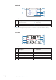
System examples
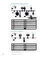
Hydra
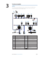
An example of a typical H5000 system. At the centre of the system is the H5000 Central
Processor Unit (CPU). All sensor information is fed back to the CPU and can be easily
controlled and confi gured via the Graphic display.
12V
12V
12V
12V
2 3
4 5 6
7
8
9
12
10
11
1
18
17
T
T
13
19
16
15
14
12V
PILOT
20
WIFI-1
No. Description No. Description
1
Masthead unit
11
Motion sensor (Heel / Trim only)
2
HV Display
12
Alarm module
3
Graphic display
13
Wireless access point WiFi-1
4
Race display
14
Central processor unit
5
Analogue display
15
Man Overboard Button - MOB
6
Zeus Touch
16
H5000 Pilot Computer
7
H5000 Pilot Controller
17
Rudder reference unit
8
RC42N compass
18
Hydraulic ram
9
GPS
19
Speed sensor
10
Baro / Air temp sensor
20
Depth sensor
T
Terminator
12V
12 Volt DC power supply
3