CONTENTS GENERAL INTRODUCTION TO B&G NETWORK ......... 2 INTRODUCTION TO NETWORK QUAD......................... 3 EXAMPLE SYSTEMS USING NETWORK QUAD........... 4 SELECTING THE DISPLAY MODE ................................ 5 USING THE SPEED KEY ................................................ 6 CALIBRATION AND OPERATING PARAMETERS........ 7 SETTING THE DISPLAY DAMPING ............................... 8 SETTING THE SPEED AND LOG UNITS ....................... 9 SPEED AND LOG CALIBRATION .........................
GENERAL INTRODUCTION TO B&G NETWORK INTRODUCTION TO NETWORK QUAD The B&G Network range of instruments is designed to be used as individual units or connected together to form an integrated navigational system. A single network cable is used to carry data and power between units. The latest technology and screened cables throughout the Network System ensure the ultimate protection from interference between units and other systems.
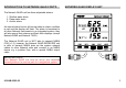
INTRODUCTION TO NETWORK QUAD CONT'D NETWORK QUAD DISPLAY UNIT The Network QUAD unit has three adjustable alarms: 1. Shallow water alarm 2. Deep water alarm 3. Anchor alarm An internal alarm buzzer will sound when an alarm condition is met and the display will flash. The alarm is broadcast to all other Network Instruments in an integrated system, they will also sound their alarms and flash their displays (except Network WIND and Network TACK). The Network QUAD unit is NOT able to transmit NMEA 0183 (v1.
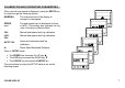
EXAMPLES SYSTEMS USING NETWORK QUAD Only one Network QUAD unit should have speed and depth sensors connected to it and set to transducer mode. Up to three more Network QUAD (set to repeater mode) or QUAD REPEATER units can be connected on to the system network. QUAD Main unit QUAD Repeater Mode QUAD Repeater Mode QUAD Speed Sensor When in repeater mode, if the data is not being received from the system network, the display will show OFF when a key is pressed.
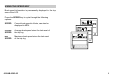
SELECTING THE DISPLAY MODE The Network QUAD unit has two operating modes. The correct mode must be selected for your Network system to operate properly. tYPEt Transducer mode, the unit uses and displays speed and depth data from sensors connected directly into the display unit. tYPEr Repeater mode, the unit operates as a repeater using data from the system network. Press TIMER key to display stored log. 610-HB-0503-05 Press SETUP key to display the current mode.
USING THE SPEED KEY Boat speed information is permanently displayed in the top area of the LCD. Press the SPEED key to cycle through the following options: SPEED Current boat speed in Knots, can also be displayed in MPH. AVERAGE Average boat speed since the last reset of the trip log. SPEED MAX SPEED Maximum boat speed since the last reset of the trip log.
CALIBRATION AND OPERATING PARAMETERS When current boat speed is displayed, press the SETUP key to cycle through the following options: DAMPING The response time of the display to changes in boat speed. SPEED KNOT The boat speed can be displayed in Knots or MPH. This setting also changes the log units to Nautical or Statute Miles. CAL Manual boat speed and log calibration. LOG CAL Manual boat speed and log calibration. AUTO CAL Automatic boat speed and log calibration.
SETTING THE DISPLAY DAMPING Damping allows the response time of the displayed speed value to be slowed down if it is to jumpy in rough weather, or to sped it up when the conditions are calm. The damping works by averaging the values over a set time period; the longer the time period the smoother the readings, however the longer it takes to see a change. Similarly the shorter it is the jumpier the readings, but the faster the response.
SETTING THE SPEED AND LOG UNITS The Network QUAD can be set to display boat speed in Knots or MPH. If boat speed is in Knots then log is in Nautical Miles. If boat speed is in MPH then log is in Statute Miles. Press SPEED key to display current boat speed. 610-HB-0503-05 Press SETUP key twice. The speed digits will blank. Press ENTER key if the units are to be changed. Use S or T to change the units. Press ENTER key to memorise the change. Press SPEED key to display current boat speed.
SPEED AND LOG CALIBRATION Before Network QUAD is used for navigation the boat speed and log have to be calibrated to ensure accuracy for your installation and the boats hull characteristics. Three methods are available with the Network QUAD unit, two manual adjustments and one automatic: MANUAL CALIBRATION 1. CAL The displayed boat speed value is corrected manually to read a known measured speed. 2. LOG CAL The units calibration figure (Hz/Knot) is manually adjusted to correct log and speed inaccuracy.
METHOD 1. - MANUAL CALIBRATION - CAL This procedure requires a reference boat speed with which to compare the Network QUAD units displayed boat speed. For example, another boat with an accurate calibrated log, or if the top speed of the boat is known this value can be entered during a sea trial to correct the displayed value. IMPORTANT NOTE: This method of calibration must not be carried out at boat speeds of LESS THAN 3 KNOTS as inaccurate values can be entered into the units memory.
METHOD 2. - MANUAL CALIBRATION - LOG CAL If the log or boat speed is in error by a known percentage then this method allows the calibration figure or LOG CAL to be adjusted by that amount. The calibration figure is measured in Hertz per knot (Hz/kt), the factory set value is 6.25. NOTE: The accuracy of this method is dependant upon the accuracy of the calculated percentage error. Using the factory set LOG CAL of 6.25 Hz/kt: • If the display is under reading by 10% subtract 0.
METHOD 3. - AUTOMATIC CALIBRATION - AUTO CAL This procedure will automatically and accurately calibrate the boat speed and log and is the recommended method for most boats. • Press the ENTER key when in line with marker A, to start run 1. The display will flash AUTO CAL 1. Press ENTER key again when in line with marker B, to freeze run 1. The display will flash, showing the distance so far for one run. • Turn the boat around for run 2 in the opposite direction over the same measured distance.
AUTOMATIC CALIBRATION PROCEDURE Distance measured on a chart Start Run 1 Stop Run 1 Stop Run 2 Start Run 2 Start Run 3 Stop Run 3 ABORTING AUTO CAL 610-HB-0503-05 14
RESETTING THE DEAD RECKONED DISTANCE This facility allows the Dead Reckoned (DR) distance log to be reset. The Network QUAD unit cannot display the DR information, however Network SPEED and Network DATA both display it. Press SPEED key to display the current boat speed. 610-HB-0503-05 Press SETUP key 6 times to display dr. The display will flash. Press ENTER key, there will be no change on the QUAD unit LCD but the dr log has been reset.
USING THE DEPTH KEY The current water depth is permanently displayed in the bottom LCD area in metres, feet or fathoms. The unit is factory set to metres. The depth displayed is from the depth datum, see DEPTH DATUM. Press the DEPTH key to cycle through the following options: CAL The Depth Datum can be adjusted so the displayed water depth is from the waterline, the depth sensor (transducer) or the keel or outdrive depth. The unit is factory set to display water depth from the transducer.
THE DEPTH DATUM - CAL The depth datum CAL is an offset calibration value used to determine the displayed information reference point. It is added to the actual measured water depth to display the depth from the waterline, the depth sensor (transducer) or the keel/outdrive depth. The Network QUAD unit has factory set CAL of zero, i.e. the depth is displayed from the transducer. The CAL value is displayed in the same units as the depth.
SETTING THE DEPTH DATUM CAL zero, depth from transducer. CAL positive, depth from waterline. CAL negative, depth from keel. NOTE: If the CAL LOCK is set then the CAL value cannot be changed. Consult your B&G dealer for further advice. Press DEPTH key to display depth datum CAL. 610-HB-0503-05 Press SETUP key to display current datum value. The display will flash. Press ENTER to adjust the datum value. The value will flash. Use S or T to adjust the value. Press ENTER to memorise the new value.
SETTING THE DEPTH UNITS The Network QUAD unit can be set to display depth in Metres, Feet or Fathoms. The selected units are used for displayed depth information on all Network instruments on the entire Network system. Press DEPTH key to display the current depth. 610-HB-0503-05 Press SETUP key twice. The depth display will go blank. Press ENTER key if the units are to be changed. Use S or T to change the units. Press ENTER key to memorise the change. Press DEPTH to display current depth.
DEPTH ALARMS The display will show OFF if the alarm is disabled or the alarm value when enabled. The value will be displayed in metres, feet or fathoms depending on the selected depth units. When the alarm condition is met the unit will sound its' internal alarm buzzer and flash DEPTH METRES. Silence the alarm by pressing any key.
ENABLING/DISABLING THE SHALLOW ALARM Press DEPTH key to display the shallow alarm. Press SETUP key, the alarm state will be displayed. Press ENTER key, the alarm state display will flash. Use S or T to enable/disable the alarm. Press ENTER to memorise the change. Press DEPTH key, the current value is displayed. Use S or T to adjust the value. Press ENTER key to memorise the new value. Press DEPTH key, the value is displayed and the alarm enabled.
ENABLING/DISABLING THE DEEP ALARM Press DEPTH key to display the deep alarm. Press SETUP key, the alarm state will be displayed. Press ENTER key, the alarm state display will flash. Use S or T to enable/disable the alarm. Press ENTER to memorise the change. Press DEPTH key, the current value is displayed. Use S or T to adjust the value. Press ENTER key to memorise the new value. Press DEPTH key, the value is displayed and the alarm enabled.
USING THE ANCHOR ALARM The Anchor Alarm uses two adjustable alarm limits. The The anchor alarm depth limits are shown alternatively when alarm will sound if the water is deeper or shallower, by the they are enabled and displayed using the DEPTH key. set values, than the original depth of water when the alarm was enabled. This allows you to adjust your anchor chain according to the tides. The Network QUAD unit has a factory set Shallow limit of 0.5m and Deep limit of 1.0m.
ENABLING/DISABLING THE ANCHOR ALARM Press DEPTH key to display ANCHOR ALARM 610-HB-0503-05 Press SETUP key, to display alarm state. Press ENTER key, the alarm state display will flash. Use S or T to enable or disable the alarm. Press ENTER to memorise the new alarm state. Press DEPTH key to display the anchor alarm.
ADJUSTING THE ANCHOR ALARM SHALLOW LIMIT Press DEPTH key to display anchor alarm. Press SETUP key twice to display the shallow value. Press ENTER key, the value display will flash. Use S or T to change the value. Press ENTER to memorise the new value and enable the alarm. Press DEPTH key to display the anchor alarm. Use S or T to change the value. Press ENTER to memorise the new value and enable the alarm. Press DEPTH key to display the anchor alarm.
USING THE TIMER/TEMP KEY Press the TIMER/TEMP key to cycle through the options: TRIP LOG A reset log that can be displayed in Nautical miles or Statute Miles. This is determined by the selection of the displayed speed units (see SETTING THE SPEED AND LOG UNITS). It also resets the Maximum and Average Speed values. LOG The Stored Log, in NM or M as above. TIMER There are three timers available: 1. 2. 3. SEA TEMPERATURE The Sea Temperature is displayed in °C Celsius or °F Fahrenheit.
RESETTING THE TRIP LOG The Trip Log is reset to zero and starts again as soon as the ENTER key is pressed. Press TIMER key to display the TRIP LOG. 610-HB-0503-05 Press SETUP key, Display flashes. Press ENTER key, the display resets to zero, and remains flashing. Press TIMER key to display the TRIP LOG.
SETTING THE TIMERS AND LAP TIMER The Lap Timer can be used to `freeze' the displayed time with any of the three Timers. Press the TIMER key to display the timers. 610-HB-0503-05 Press SETUP key 10 min. 1 5 min. 2 Count-up 3 The display will flash. Press ENTER key, the display is set to the selected starting value. The timer starts to count. Press TIMER key, the display stops flashing and the timer is running. Press TIMER key to freeze the displayed time.
SETTING THE TEMPERATURE UNITS The sea temperature can be displayed in Celsius or Fahrenheit. Press TEMP key until the sea temperature is displayed. 610-HB-0503-05 Press SETUP key once to display the current units. Press ENTER if the units are to be changed. The display will flash. Use S or T keys to change the displayed units. Press ENTER key to memorise the new units. Press TEMP key to display sea temperature.
CALIBRATING THE TEMPERATURE SENSOR Temperature calibration should only be carried out when the built-in sea water temperature sensor (part of the speed sensor) is considered to be inaccurate. The temperature of the water will have to be measured with an accurate temperature sensing device, this value can then be entered into the Network QUAD unit. In the following example the unit is displaying a reading of 10.4°C, the water temperature is known to be 11.4°C.
USING THE LIGHTS KEY The Network QUAD Display unit has 3 levels of illumination and off, controlled by the LIGHTS key. It also changes the illumination level of the key legends. The LIGHTS key is always illuminated so even in complete darkness the key can be located.
NETWORK ALARMS The Network QUAD unit has an internal buzzer that will sound when an alarm condition is met on a Network unit that has alarm functions ie. Network DEPTH and Network QUAD for depth alarms and Network PILOT for Watch Alarm and Off Course alarms. The unit will also display which alarm is activated. NETWORK PILOT ALARM DISPLAYS (NOT QUAD UNIT) The Watch Alarm is a count-down timer with is activated at the end of the preset count-down period. The display alternates between the messages below.
FAULT AND ERROR MESSAGES NETWORK PILOT FAULT DISPLAY (NOT QUAD UNIT) UNIT INTERNAL ERRORS If the Network PILOT should have a fault the autopilot computer unit will send a message to all other Network Display Units. The Network units will alternately display the following message; the actual fault will have to read from the Network PILOT Display unit.
INSTALLATION MOUNTING THE UNIT The display heads are supplied with a clip-in mounting bracket which allows for easy installation, access from behind is not necessary to secure the unit in place. However to prevent theft and permanently fix the unit in position, locking studs and thumb nuts are supplied. Use the cutting template supplied to mark the centres of the holes for the self-tapping screw, the fixing stud holes and the mounting bracket.
INSTALLATION DATA 110.0mm 25.0mm 65.0mm Network QUAD Locking stud fixing Speed sensor connector 110.0mm Depth sensor connector SPEED DEPTH TIMER SETUP TEMP LIGHTS ENTER Network connector Mounting bracket Network & Power connector Rubber Gasket 82.0mm Fit the gasket around the mounting bracket 82.0mm Gasket Display Unit Sun-cover 70.
SPECIFICATION PHYSICAL PARAMETERS Construction Window Display Dimensions: Weight: High impact ABS plastic Acrylic Back-lit Liquid Crystal Display: Large Digits: 15mm (0.6") Small Digits: 10mm (0.4") 110 x 110 x 25.4mm (4 x 4 x 1") Requires 65mm (2.6") depth behind bulkhead for display barrel 0.3 Kg (0.66lbs) Power Supply Operating Current Protection -10 à+55°C, +14 to +131F @ 93%RH -25 à+70°C, -25 to +70C @ 95%RH Up to 95%RH Fully sealed front, suitable for bulkhead cockpit mounting.