Triton Display Installation Manual ENGLISH bandg.
Preface As Navico are continuously improving this product, we retain the right to make changes to the product at any time which may not be reflected in this version of the manual. Please contact your nearest distributor if you require any further assistance. It is the owner’s sole responsibility to install and use the instrument and transducers in a manner that will not cause accidents, personal injury or property damage. The user of this product is solely responsible for observing safe boating practices.
Declarations and conformance This equipment is intended for use in international waters as coastal sea area administered by countries of the E.U. and E.E.A. B&G Triton Display complies with the following regulations: • CE under EMC directive 2004/108/EC • level 2 devices of the Radio communications (Electromagnetic Compatibility) standard 2008 B&G Triton Display meets the technical standards in accordance with Part 15.103 of the FCC rules.
The software This manual is written for B&G Triton Release to Market 1 (RTM1). Please check web site for details on the current release version. ¼ Note: The menu route shown above is an example only and may not match the software installed on your unit! ¼ Note: To update the software you will need a compatible multifunction display / chartplotter running on the network. eg. B&G Zeus multi function display (MFD).
Contents 1 Preface 7 Introduction 8 Overview 9 10 Menus Check the contents 12 Installation 12 12 13 14 14 Choosing a location Viewing angles Fitting with mounting clip Fitting with retention bracket Multiple displays 15 Wiring 15 17 18 19 Introduction to NMEA 2000 (SimNet) Daisy chaining the Triton display Drop cable connection of the Triton display Typical network example 20 Display 20 27 Setup wizard Sources 30 Calibration 30 31 31 35 35 36 Depth Sea temperature Boat speed Apparent
6| 38 Autopilot 39 39 44 46 47 48 48 50 Autopilot Setup Dockside Sea trial Pilot response Wind response Sea state filter Sailing Automatic steering 57 Troubleshooting 58 Technical Specifications 58 59 60 Display Dimensional drawing Spares & Accessories Contents | B&G Triton Display Installation Manual
Introduction The Triton Display utilizes a unique bonded 4.1-inch sunlight viewable LCD display to offer clearly read sailing information, including wind, speed, depth, heading, pilot status, log, timer and much more. High contrast and a 155˚ viewing angle provide excellent readability, whilst the bonded display ensures there is no chance of condensation occurring regardless of the conditions. Power consumption is extremely low for this class of product - 155 mA at 13.
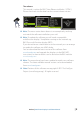
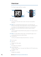
Overview The Triton Display and Pilot Controller 1 5 6 4 3 2 7 8 9 1. Display 2. Menu / Enter key Used to enter the main menu, select sub menus and confirm selection. ¼¼ Note: Press and holding the Enter key for 3 seconds takes you directly to the display setup lighting level screen. If the lighting level is set below 5 it will automatically increase to 5. Use the up and down keys to set the desired level and press Enter to confirm. 3.
Menus Under normal operation, the unit will power up displaying the most recently used data page. To enter the menu use the Menu/Enter key. 1 4 2 3 1. 2. 3. 4.
Check the contents Triton Instrument Display Mounting Clip Sun Cover Fixing Screws Additional Retention Bracket Threaded rods, Washers, and Fasteners for Retention bracket 0.
Installation Manual Quick Reference Guide Operation Manual DVD Installation Manual & Operation Guide 80.0 mm (3.15") 123 mm (4.84") 118 mm (4.64") 98.0 mm (3.86") Triton Display 89.0mm (3.5") *988-10136-001* CL 3.5 mm 0.14 ” required for removing when flush mounted IMPORTANT. Do not use this template if it has been rescaled by copying or printing. If this is not the original, or is a print from a file, please check the dimension lines below are to scale before use. IMPORTANT.
Installation The Triton display may be mounted via a flush mounting clip or with the retention bracket attached to the rear of the unit. Choosing a location Choose the mounting locations carefully before you drill or cut. The display should be mounted so that the operator can easily use the controls and clearly see the display screen. Be sure the chosen location allows access for routing the cables. Ensure that any holes cut will not weaken the boat’s structure.
Fitting with mounting clip Use the template to cut the required size hole in the chosen location. At the same time mark the holes to be drilled for the fasteners. Take care to be as accurate as possible when cutting out the mounting hole - the mounting clip should be a close, but not tight fit in the hole. If the clip requires pressure to get in to position, there is a high chance it will distort, and not retain the display as well as intended.
Fitting with retention bracket The Triton display may be mounted using only the mounting clip, or may be secured additionally with the retention bracket. In order to secure the bracket, adequate rear access must be available to fit the fasteners. Before fitting the display in to the mounting position, firmly wind the threaded rods into the back of the Triton display by hand. Place the display in to position and fit the retention bracket, followed by washers and fasteners.
Wiring The B&G Triton Display can be connected to either an NMEA2000 or SimNet network. There is no separate power cable, as the unit is powered from the network. There are two Micro-C connectors on each display, allowing for daisy chaining, which greatly increases the ease of connecting multiple displays that are in close proximity, and can save in cable weight and loom size. Note this method is approved in SimNet networks, but not in NMEA 2000 networks.
• • • An NMEA 2000 network needs to have a terminator at each end of the backbone. A terminator can be one of the following: • a power cable with built in terminator • a terminated blanking plug • a wind transducer (terminator is in the mast head unit as opposed to mast cable). Certain Simrad products have two Micro-C or SimNet connectors, which can be made to be an in line component of the backbone.
Power the network An NMEA 2000 network requires its own 12 V DC power supply protected by a 5 amp fuse or breaker. In smaller NMEA 2000 systems, the power connection may be made anywhere in the system, For larger systems introduce power at a central point in the backbone to “balance” the voltage drop of the network. Use a power cable without termination. ¼¼ Note: When joining an NMEA 2000 network to a SimNet network, it is not necessary to introduce power to both.
Drop cable connection of the Triton display 1 1 2 2 4 3 4 4 1 2 1. 2. 3. 4.
CHART RADAR ECHO LTW NAV Wiring | B&G Triton Display Installation Manual INFO LTW PAGES PWR 0 6 MNO 9WXYZ 3 DEF OUT WIN 5 JKL 2 ABC STBY AUTO 4 GHI GO TO VESSEL 7 PQRS 8 TUV 1MOB IN MENU PLOT MARK LTW LTW CHART RADAR ECHO Rx Tx NAV B IIT INFO P WR PAGES 2 ABC 5 JKL STBY AUTO 0 7 PQRS 8 TUV 4 GHI 1MOB IN MENU PLOT MARK PWR 9WXYZ 6 MNO 3 DEF OUT WIN GO TO VESSEL Typical network example 120 | 19
Display This section focuses on initial setup of settings that should require infrequent adjustment. For regularly used features, refer to the Operation or Quick Guide. Setup wizard The first time a new Triton display is turned on, the Setup Wizard will guide you through essential configuration items. • Language • Boat Type • Set Date and Time Format • Unit Selection • Display Mode The available settings and descriptions are given in the following section on the Setup Menu.
System setup In display setup you can set the lighting zone, enter night mode and change the lighting level. ¼¼ Note: Press and hold the ‘Enter’ key for 3 seconds will take you directly to the display setup lighting level screen. If the lighting level is set below 5 it will automatically increase to 5. Use the up and down keys to set the desired level and press ‘Enter’ to confirm. Lighting zone All units in the selected lighting zone will mirror each other’s light settings. Default setting is Network.
Units Set the preferred unit of measurement you want data to be displayed in.
Language The display can be set to different languages to suit your preference. Display mode There are 3 display functionality modes. Highlight the desired mode and press ‘Enter’ to select. Instrument display only Displays instrument data only. No Pilot data page is viewable. Pilot display only Displays Pilot data only. No instrument data pages are viewable.
Boat type Allows selection between Power Boat or Sail Boat. Boat type changes the icon on the depth plot page, as well as determining available features and operational modes for the autopilot. Software information Shows the software version currently installed on the display. Press ‘Enter’ or the ‘Page’ key to navigate back to the menu.
System From the system menu there are several options to reset the system, place the display into simulator and get the current software information. Reset options There are a variety of reset options available from the system menu. ¼¼ Note: Whenever a reset option is selected there will be a dialog box asking you to confirm that you wish to reset before any further action is taken. If you wish to cancel the reset, selecting No will return you to the system menu.
Reset to Factory Resets the current display to the default settings. When the unit is restarted you will see the original startup wizard asking you to set the display. Warning: All settings for instrument and Pilot will be restored to factory default. The Pilot will need to be commissioned before use. Simulator Simulator mode sends simulated data to the display. Warning: It is not advisable to enter simulator mode when using your instrument system as a navigation aid.
Sources A data source can be a sensor or a device connected to the NMEA2000 network, providing information and commands to other networked devices. The data sources are normally configured at first time turn on. It should only be necessary to update this data if a new source is added, source is missing (sensor failure), source has been enabled/ disabled, sensor replaced or a network reset. Auto select The Auto select option will look for all sources connected to the instrument system.
The operator will be noted when the auto select process is completed. ¼¼ Note: If more than one source is available on the network you can chose your preferred source from the sources menu. See “Manual source selection” for more information. Manual source selection If more than one source is available for an item, the preferred source may be selected manually. As an example, the following illustrations show how the compass source is changed. Select the preferred data source.
Selecting a device from the list will show you an information pane with details of that device. Some devices such as an RC42 compass store their configuration, calibration and offset data in their own memory and not in the display memory. For devices of this type you can check the data information, configure and calibrate the device by selecting Options. Data The data list shows the data type that the device is transmitting.
Calibration Depth A typical transducer installation is through the hull in front of the keel. A datum (offset value) can be set, such that the depth display refers to either the water line or the base of the keel. +VE: Positive Datum for Waterline (0.0) - VE: Negative Datum for Keel Setting the depth offset displays depth readings from directly below the keel or propellers of the boat, or from the waterline to the seabed.
Sea temperature If a suitable temperature sensor is fitted, the system will monitor the sea temperature. The offset value to be entered should adjust the temperature reading from the sensor to match a calibrated thermometer when submersed in the water Boat speed Speed calibration is necessary to compensate for hull shape and paddlewheel location on your boat. For accurate speed and log readings, it is essential that the paddlewheel is calibrated. Boat speed values can be shown in knots, kph or mph.
1. Bring the boat up to cruising speed (above 5 knots) 2. Select Auto on the Boat speed calibration page 3. When the calibration is completed the Boat speed calibration scale will show the adjusted percentage value of the boat speed. USE SOG as boat speed If boat speed is not available from a paddle wheel sensor it is possible to use speed over ground from a GPS. SOG will be displayed as boat speed and used in the true wind calculations and the speed log.
Distance reference This facility enables the user to calibrate the log accurately and simply. Calculations are performed by the display that works out the boat speed over a known distance. To calibrate the boat speed via a distance reference you will need to complete consecutive runs, under power at a constant speed made along a given course and distance. ¼¼ Note: To eliminate the effect of tidal conditions it is advisable to perform at least two runs, preferably three, along the measured course.
Distance reference diagram Referring to the diagram reference diagram, A and B are the markers for each run and X is the actual distance for each run as ascertained from a suitable chart or GPS for example. A X B Start Run 1 Stop Run 1 Start Run 2 Stop Run 1 Start Run 3 End Calibration As the boat passes marks A and B on each run, instruct the system to start (Start Run) and stop (Stop Run) and finally OK to end calibration (End Cal Runs).
Apparent wind This provides an offset calibration in degrees to compensate for any mechanical misalignment between the masthead unit and the center line of the vessel. To check the masthead unit alignment error we recommend you use the following method which involves a sailing trial. Sail on a starboard tack on a close hauled course and record the wind angle, then repeat the process on a port tack. Divide the difference between the two recorded numbers and enter this as the wind angle offset.
Compass heading The compass offset compensates for fixed errors (misalignment) between the compass sensor and the direction of the boat. To accurately enter a compass offset, the boat’s heading must be referenced to, for example: a calibrated bowl compass. The offset value will be the difference between the known source and the currently displayed heading.
Decimal places It is possible to change how many decimal places speed and sea temperature data will be displayed with. Choose how many decimal places you wish to have shown for that specific data type. Magnetic variation Adjust how the system handles magnetic variation. Auto: Automatically calculates variation based on position and date. Manual: If variation is not available enter a value manually. Sounds: Turn the keypress and alarm sounds on or off.
Autopilot If an AC12 or AC42 autopilot computer is connected to a Triton display and AP controller, autopilot control and setup functionality will be made available. Warning: The installation settings must be performed as part of the commissioning of the Pilot system. Failure to do so correctly may prohibit the Pilot from functioning properly! The Installation menu can only be accessed in Standby mode.
Autopilot Setup Before the Pilot can be used you must first commission it and complete all of the dockside procedures before it is operational. Dockside The dockside procedures are initiated from the commissioning dialog. Completed procedures are labelled with a tick.
Boat Type Type of boat selected will affect the steering parameters, and the functions available in the autopilot system. The options are: Planing, Displacement, Sail and Outboard. ¼¼ Note: Wind mode is only available if boat type is set to sail. Drive voltage (V) Sets the drive voltage type to 12 or 24V Rudder Feedback Calibration Make sure the unit is installed and aligned as per instruction in the AC12/42 Installation manual.
¼ Note: Many boats have ±45° (90° H.O. - H.O.) rudder angle as standard. So if you are not going to make any adjustment to the displayed angle you should still highlight the reading and confirm. This is necessary to prevent the rudder from hitting the end stops. Set Rudder to 0 (zero) Bring the rudder to midship position and confirm. This will adjust an incorrect reading caused by misalignment of the rudder feedback unit.
Rudder drive Ensure that the rudder information is set correctly before you continue with the Dockside commissioning. Drive voltage (V) Sets the drive voltage to the type installed on the vessel 12 or 24V Drive engage Drive engage has the following settings: Auto and Clutch. Clutch: This is the default setting and it allows you to steer the boat from the helm when in Standby mode. A clutch will be engaged on the drive unit locking out the steering when Auto is selected.
Rudder deadband The rudder deadband function is adaptive and is continuously updating. It prevents the rudder from hunting and the adaptive function optimizes the deadband to the speed of the boat and the load on the rudder. If the auto-setting does not perform properly due to high inertia from the wheel, it can be adjusted manually. Find the lowest possible value that will prevent the rudder from continuous hunting. A wide deadband will cause inaccurate steering.
Sea trial After completing the Pilot calibration and all settings in the installation menu, you will need to perform a final sea trial. ¼¼ Note: The sea trial should be conducted in open waters at a safe distance from other traffic.
Autotune Autotune is a feature that automatically sets the most important steering parameters (Rudder and Counter Rudder) by taking the boat through a number of S-turns. The scaling factors of the parameters are also set automatically as a function of the boat type selection performed in the Dockside menu. The automatic tuning process is also verifying/adjusting the Rudder zero alignment made in Dockside setup.
After the Autotune has been completed the rudder must be controlled manually, as the autopilot has returned to Standby mode. The Automatic tuning function will take control of the boat and perform a number of S-turns. ¼¼ Note: Autotune must always be performed in open waters at a safe distance from other traffic. The Automatic tuning function may take from 2 to 3 minutes to complete. To stop the Autotune, press the ‘Enter’ key.
Selection of Hi / Lo parameters The Manual select item has three alternatives: Auto – Hi – Lo. • • Auto is automatically set by speed input Hi or Lo must be set manually when there is no speed input The sub-headline in the display shows the active parameter set and how it is selected. Wind response Verify that the difference between Set Heading and the actual heading is at an acceptable minimum.
Sea state filter The Seastate filter is used to reduce rudder activity and autopilot sensitivity in rough weather. Off: Seastate filter is disabled. This is default. Auto: Reduces rudder activity and autopilot sensitivity in rough weather by an adaptive process. The Auto setting is recommended if you want to use the Seastate filter. Manual Linked to the Response control setting in the Main menu.
Tack angle In Wind function Auto mode the set tack angle replaces a similar change of the set course using the starboard and port keys. Range Change per step Default Units 50 - 150 1 100 º Wind function With Wind function set to auto, the autopilot will automatically select between apparent and true wind steering. Auto is default and recommended for cruising. When the boat is running, it will also be surfing on the waves.
Layline steering Layline steering is useful when navigating. Cross Track Error (XTE) from the navigator will keep the boat on the rhumb line. If the XTE from the navigator exceeds 0.15 nm, the autopilot will calculate the layline and track towards the waypoint.
Automatic steering The Automatic steering menu contains steering parameters for compass steering, wind steering and nav steering. These steering parameters can be changed if needed to improve sailing performance. From this menu you can set the transition speed, high and low boat speed parameters to account for changes in boat speed, rudder angle, wind and compass settings.
¼ Note: The two most important parameters that determine the performance of the automatic steering are Rudder Gain and Counter Rudder. Rudder Sets the rudder gain which is the ratio between the commanded angle and the heading error.
Counter rudder Counter Rudder is the parameter that counteracts the effect of the boat’s turn rate and inertia. For a short time period it is superimposed on the proportional rudder response caused by the heading error. It may sometimes appear as if it tends to make the rudder move to the wrong side (counter rudder). The best way of checking the value of the Counter Rudder setting is when making turns. The figures illustrate the effects of various Counter Rudder settings.
Minimum rudder Some boats may have a tendency to not respond to small rudder commands around a set course because of a small rudder, rudder deadband or Whirls/disturbance of the water-stream passing the rudder. Turning the Minimum Rudder function on, may improve the course keeping performance on some boats, but will increase the rudder activity. Range Change per step Default Units Off - 5 0.
The Minimum wind angle applies for the tack-prevent function. It also applies when the autopilot is operating in WindNAV mode. You can select different minimum wind angles for port and starboard. The difference between port and starboard will be taken into account when calculating the Distance To Turn (DTT).
Resetting the Pilot Warning: all previous Pilot settings will be lost! Before engaging the Pilot the commissioning and calibration process must be completed.
Troubleshooting Issue Solution Unit does not power up • • Unit does not show data for a specific source • • Unit does not show any data from any connected source or Unit data sources intermittently drop out. • • • • • • Check that the NMEA2000/ SimNet network has 12V connected. Try connecting to a different network cable in case power wires damaged internally. In the advanced setup menu, select sources, and manually select the required data source.
Technical Specifications Display Weight Power consumption Network load 0.28 kg (0.6 lbs) 150 mA at 13.5V Maximum 10 Triton displays Colour Size Type Resolution Illumination Black 4.1” (Diagonal) 4:3 Aspect ratio Transmissive TFT-LCD White LED back-light 320 x 240 pixels White (day mode) / Red (night mode) Environmental Protection IPX7 Safe distance to compass 0.3 m (1.0 ft.
Dimensional drawing 115 mm (4.53") 120mm (4.72") 123 mm (4.84") 118 mm (4.64") Suncover outline 84 mm (3.31") 17 mm (0.67") LTW 18.9 mm (0.74") 40mm (1.
Spares & Accessories Part Number Description 000-10637-001 Triton wind sensor 000-10652-001 Triton wind sensor pack with 20 meter mast cable 000-10647-001 Triton wind sensor pack with 35 meter mast cable 000-10613-001 RC42N, Rate compass, micro-c 000-10614-001 Cable, micro-c, right angle interconnect 000-10615-001 Sun cover, Triton display ¼¼ Note: new accessories are continuously being developed, check with your B&G dealer or on www.bandg.com for details on new products.
N2584 *988-10222-001*