Triton Operation Manual ENGLISH bandg.
Preface As Navico are continuously improving this product, we retain the right to make changes to the product at any time which may not be reflected in this version of the manual. Please contact your nearest distributor if you require any further assistance. It is the owner’s sole responsibility to install and use the instrument and transducers in a manner that will not cause accidents, personal injury or property damage. The user of this product is solely responsible for observing safe boating practices.
The software This manual is written for B&G Triton Release to Market 1 (RTM1). Please check web site for details on the current release version. Note: The menu route shown above is an example only and may not match the software installed on your unit! Note: To update the software you will need a compatible multifunction display / chartplotter running on the network. eg. B&G Zeus multi function display (MFD).
Contents 7 Operation 7 8 9 13 14 15 16 17 18 19 The Triton Display and Pilot Controller Pages Default pages Replacing a data page Template pages Customizing a template page Auto scroll Timer Log Alarms 23 Setup 23 24 29 30 31 31 32 32 32 33 33 34 Sources Device list Time & Date Units Display mode Display setup Damping Decimal places Magnetic variation Sounds System Diagnostics 35 Autopilot 35 35 36 37 37 38 38 39 39 40 42 42 Overview Operation Pilot Controller Turning the Pilot on / off Autopilot
| 57 Maintenance 57 General maintenance 59 Specifications 59 Technical specifications 60 Dimensional drawings 60 60 Display Pilot controller 61 Menu flow chart Contents | Triton Operator Manual
1 Operation The B&G Triton system is a networked multifunction instrument display and Pilot controller. The display shows speed, depth, heading, position, wind and environmental data measured by sensors and other equipment connected to the system. Navigational data, engine/battery status and vessel parameters such as accumulated log and rudder angle may also be displayed. The instrument calculates speed trim, wind, trip distance and time, average speed, set and drift parameters.
Pages From new the display shows eight default data pages. Data pages show a variety of boat data and information available from sensors and devices on the Network. The display default pages show: Basic speed/depth, wind composite, basic wind/speed, steering, depth history, GPS, highway and autopilot. Each press of the page key will change the current data page to the next preselected page in the cycle. Note: Pressing the page key will change the data pages in sequence and in continuous rotation.
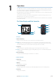
Default pages Basic Speed / Depth Two line data display. Boat speed and Depth Wind Composite The wind composite page presents the following information: 1 2 3 5 6 7 4 8 9 1 Apparent wind speed (AWS) 2 Red - Close hauled port tack 3 Boat orientation. (Always pointing forwards) 4 True wind speed (TWS) 5 Apparent wind angle (AWA) 6 Green - Close hauled starboard tack 7 Apparent wind angle graphic 8 True wind angle graphic 9 True wind angle (TWA) Basic Wind / Speed Two line data display.
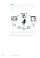
Steering The Steering page presents the following information: 6 1 2 3 4 5 7 8 9 10 1 Compass graphic (Heading) 2 Heading 3 Bearing to waypoint (BTW) 4 Off track limit 5 Rhumb line 6 Bearing to waypoint indicator 7 Course over ground (COG) 8 Cross track error (XTE) R = Right / L = Left 9 Cross track error graphic 10 Boat position from rhumb line Depth History Current depth and histogram of recorded depth data.
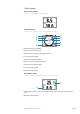
GPS The GPS page presents the following information: 2 3 6 7 1 4 5 8 1 Coordinate system 2 Boat position (Latitude & Longitude) 3 Course over ground (COG) 4 Local time 5 Speed over ground (SOG) 6 Bearing to waypoint (BTW) 7 Estimated time of arrival (ETA) 8 Distance to waypoint (DTW) Note: GPS information relies on a suitable GPS connected to the network and selected on the display as the current GPS.
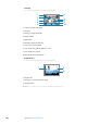
Autopilot The Autopilot page presents the following information: 5 6 7 8 1 2 3 4 1 Response mode 2 Pilot mode 3 Compass graphic (Heading) 4 Rudder angle graphic 5 Set heading / Wind angle / Rudder angle 6 Current heading / Wind angle 7 Set heading indicator - Green = Starboard / Red = Port 8 Heading Pilot modes The current heading and Set heading information will change on the display depending on which mode the pilot is in.
Response modes The response mode is next to the Pilot mode symbol. Select auto or hi/low manual modes from the pilot response settings in the pilot menu. Response Mode Auto Hi Lo Symbol Hi-A Lo-A Hi-M Lo-M Description When set to Auto the pilot will automatically select a high or low response mode determined by boat speed and wind angle Manual selection of Hi response mode Manual selection of Lo response mode Replacing a data page Go to the pages menu.
Template pages There are nine template pages that can be configured to display specific data suited to the user. Chose from the following: Template Page Symbol Single Line One piece of data Two Line Two pieces of data on a split level, top and bottom Four Panel Horizontal Four pieces of data. One on top and three below Four Panel Equal Four pieces of data. Split equally Nine Panel Nine pieces of data. Split equally 0.
Customizing a template page Once selected you can change the displayed data by editing the page. Change data You can edit a template page so it displays the specific information that you require. Note: A template page cannot be edited until it has been selected as one of the eight data pages. To change the display data shown on a template page first select the template from the pages menu. In the action menu select Change Data.
Auto scroll When selected, auto scroll automatically scrolls between the enabled pages at a timed interval predetermined by setting the desired scroll time in the auto scroll settings menu. Include in auto scroll To include a page in auto scroll, go to the auto scroll settings in the action menu of the specific page and select Include in auto scroll. Once selected a tick will appear in the check box.
Timer The timer can be used as a countdown timer to a race start and as a means of measuring the time elapsed after a race start or for any other timed operation. Note: The timer is by default shared between interconnected displays on the network. All timer values will be identical. The timer can be started at any time by selecting Start Timer from the timer setup menu. If the Start value is set to zero (00:00) when the timer is started the timer will begin counting up, recording the elapsed time.
Reset Timer Selecting Reset timer will reset the timer to the start value. If the timer was running, it will continue to run from the start value. Start Trip on Running When selected the trip log will record your time and millage from the moment the countdown clock begins counting up from zero. Nearest Full Minute When the timer is counting down selecting Nearest Full Minute will synchronize the time up or down to the nearest full minute.
Reset trip and time To reset the trip and time to zero select Reset trip and time. Alarms If you have the relevant sensor connected to the network you can enable the corresponding alarm by selecting it from the Alarms list. Alarm on / off Turn an alarm on or off from the alarm list. A tick symbol next to the alarm in the alarm list will indicate that the alarm is on.
Alarm indication The alarm system is activated if any alarm settings are exceeded. When an alarm is notified, the alarm will be indicated with an alarm text and with an audible alarm. There are two types of audible alarm indication. Single alarm tone or continuous alarm tone. Note: See Alarm settings for further details on how to set an alarm. Note: If a Pilot is not on the network all Pilot alarms will be greyed out and will not be accessible.
Alarm types Alarm Value Disable all alarms OFF Alarm description Type All alarms off.- NO Alarms will be raised! Cont’ Shallow water m Shallow water limit - Meters Cont’ Deep water m Deep water limit - Meters Cont’ High wind kn Max wind speed - Knots Cont’ Off course nm Max off course distance - Nautical miles Cont’ N/A Use when at anchor. The alarm will sound when there is a significant change of depth caused by a change in tide or boat drifting into deeper or shallower water.
| Operation | Triton Operator Manual
2 Setup Sources A data source can be a sensor or a device connected to the NMEA2000 network, providing information and commands to other networked devices. The data sources are normally configured at first time turn on. It should only be necessary to update this data if a new source is added, source is missing (sensor failure), source has been enabled/disabled, sensor replaced or a network reset. Auto select The Auto select option will look for all sources connected to the instrument system.
Manual source selection If more than one source is available for an item, the preferred source may be selected manually. As an example, the following illustrations show how the compass source is changed. Select the preferred data source. The selected source will be indicated by a tick in the check box. Device list Shows a list of devices connected to the Network. Selecting a device from the list will show you an information pane with details of that device.
Boat speed Speed calibration is necessary to compensate for hull shape and paddlewheel location on your boat. For accurate speed and log readings, it is essential that the paddlewheel is calibrated. Boat speed values can be shown in knots, kph or mph. Your preferred unit of measurement can be set in the units page of the setup menu.
Manual adjustment of boat speed Adjust the boat speed manually by selecting the Boat speed percentage slider. Adjust the percentage up or down as desired. Confirm the value. Select OK once complete. Distance Reference This facility enables the user to calibrate the log accurately and simply. Calculations are performed by the display that works out the boat speed over a known distance.
Distance reference diagram Referring to the diagram reference diagram, A and B are the markers for each run and X is the actual distance for each run as ascertained from a suitable chart or GPS for example. A X B Start Run 1 Stop Run 1 Start Run 2 Stop Run 2 Start Run 3 End Calibration As the boat passes marks A and B on each run, instruct the system to start (Start Run) and stop (Stop Run) and finally OK to end calibration (End Cal Runs).
The offset value to be entered should represent the distance between the face of the depth transducer, and the lowest part of the boat below the waterline, or the distance between the face of the depth transducer and the water surface. Sea Temperature If a suitable temperature sensor is fitted, the system will monitor the current sea temperature.
Compass Heading The compass offset compensates for fixed errors (misalignment) between the compass sensor and the direction of the boat. To accurately enter a compass offset, the boat’s heading must be referenced to, for example: a calibrated bowl compass . The offset value will be the difference between the known source and the currently displayed heading.
Units Set the preferred unit of measurement you want data to be displayed in.
Display mode There are 3 display functionality modes. Highlight the desired mode and press ‘Enter’ to select. Instrument display only Displays instrument data only. No Pilot data page is viewable. Pilot display only Displays Pilot data only. No instrument data pages are viewable. Pilot when engaged Possible to view instrument data pages at all times and Pilot data when a Pilot system is installed and connected to the network. Note: The Pilot page is automatically displayed when the Pilot is engaged.
Boat type Select the type of boat that is installed on. Chose either Sail or Power depending on the vessel. Damping The damping rate effects the frequency that the sensor data is updated on the display, the greater the damping value the smoother the number change will be but the slower the response will be to data change. Decimal places It is possible to change how many decimal places speed and sea temperature data will be displayed with.
Sounds Turn the keypress and alarm sounds on or off. Note: Silencing the alarm sound does not deactivate the alarms. When an alarm is activated the warning notification will be shown on the display regardless of the sound being on or off. System From the system menu there are several options to reset the system, place the display into simulator and get the current software information. Reset options There are a variety of reset options available from the system menu.
Reset to Factory Resets the current display to the default settings. When the unit is restarted you will see the original startup wizard asking you to set the display. Warning: All settings for instrument and Pilot will be restored to factory default. The Pilot will need to be commissioned before use. Simulator Simulator mode sends simulated data to the display. Warning: It is not advisable to enter simulator mode when using your instrument system as a navigation aid.
Autopilot 3 Overview If a Pilot control system is installed and connected to the network then you will be able to see the Pilot functionality on your display. The autopilot is designed to maintain an accurate course in all sea conditions with minimal movements to the rudder. As the autopilot steers so accurately, it will get you to your destination faster and more efficiently, especially when navigating to a waypoint or following a route.
Pilot Controller Keys The Pilot controller is operated by 7 keys, these are used to operate the pilot and adjust pilot parameters. Connectors The Pilot controller is equipped with 1 Network connector at the rear. Network The pilot controller can be connected at any point on the network. Keys Function Mode: Changes the Pilot mode. When in Auto mode pressing the mode key will change the Pilot to Wind mode.
Turning the Pilot on / off Engaging the Pilot At anytime while the Pilot is disengaged press the ‘Auto’ key to engage the Pilot. The Pilot will steer the boat on the current selected course. Disengaging the Pilot At any time the Pilot is engaged press the ‘Off ’ key to disengage the Pilot. The Pilot will go into standby mode and you will be required to take manual control of the helm.
Autopilot symbols More Pilot modes are available via a compatible chart plotter connected to the network. Any Pilot mode selected via the chartplotter will be shown on the display. Below is a list of Pilot modes and their symbols accessible via the Pilot controller.. Mode Symbol S A W N NFU Function / Mode Standby Auto (Compass) Wind Navigation Non Follow Up (Power steer) Note: The Pilot mode can be selected or changed at anytime via the display or compatible chart plotter connected to the Network.
Standby mode (Manual helm steering) The autopilot must be in Standby mode when you steer the boat at the helm. You can switch the autopilot to Standby mode from any operation by a short press on the ‘Off ’ key. Auto mode (Compass steer mode) When the ‘Auto’ key is pressed, the autopilot selects the current boat heading as the set course. The autopilot will keep the boat on the set course until a new mode is selected or a new course is set with the ‘Course’ keys.
Wind mode When the autopilot is set to Wind steer mode the Pilot uses the current apparent wind angle and maintains that angle as the auto steered course. Press the ‘Mode’ key until the wind mode symbol is visible in the mode field on the display. The autopilot will keep the boat on that wind angle until a new mode is selected or a new wind angle is set with the ‘Arrow’ keys. Once a new angle is selected, the boat will auto steer to maintain the new angle.
Pilot - Wind page The wind display presents the following information: 1 2 3 5 6 7 8 4 1 Response mode 2 Pilot mode: W = Wind mode 3 Compass graphic (Heading) 4 Rudder angle graphic 5 Wind angle 6 Apparent / True Wind angle (depending on wind setting) 7 Set heading indicator - Green = Starboard / Red = Port 8 Heading The set heading and set wind angle are entered from the compass heading and the masthead unit at the moment the Wind mode is selected.
Tack & Gybe in wind mode To tack or gybe in wind mode press both 1º course keys on the Pilot controller. When you enter a command to tack in wind mode a pop up will appear on screen asking you to confirm the desired action. Press ‘Enter’ to accept. Pressing ‘Enter’ on the display or ‘Auto’ on the Pilot controller will activate the tack/gybe function and the boat will start turning to the opposite wind angle.
to select Yes to confirm before navigation steer mode will be engaged.
The prompt display shows the name of the next waypoint, the bearing of the rhumb linefrom the previous waypoint to the destination waypoint, the required course change and the direction in which the boat will turn. Note: If only one waypoint has been entered the bearing will be from the boat’s position to the destination waypoint. Note: For Cross Track Error, the number of decimals shown depends on the output from the GPS/chart plotter. Three decimals give more accurate course keeping.
4 Autopilot settings Installation menu Warning: The installation settings must be performed as part of the commissioning of the Pilot system. Failure to do so correctly may prohibit the Pilot from functioning properly! The Installation menu can only be accessed in Standby mode.
Dockside The dockside procedures are initiated from the commissioning dialog. Completed procedures are labelled with a tick. The following menu items are accessible and can be set up in the Installation menu: • • • • • • • • Boat type Rudder feedback Drive voltage Drive engage Rudder test Depth calibration Minimum wind angle Nav change limit Boat Type Type of boat selected will affect the steering parameters, and the functions available in the autopilot system.
Max port • Manually move the helm to port until the rudder stops at port lock hard over. • Adjust the displayed angle the same way as for starboard rudder. • Confirm Rudder feedback calibration to port by selecting Next. Note: Many boats have ±45° (90° H.O. - H.O.) rudder angle as standard. So if you are not going to make any adjustment to the displayed angle you should still highlight the reading and confirm. This is necessary to prevent the rudder from hitting the end stops.
Drive voltage (V) Sets the drive voltage to the type installed on the vessel 12 or 24V Drive engage Drive engage has the following settings: Auto and Clutch. Clutch: This is the default setting and it allows you to steer the boat from the helm when in Standby mode. A clutch will be engaged on the drive unit locking out the steering when Auto is selected. Auto: This setting is implemented for future use. Always use the Clutch (default) setting.
Sea trial After completing the Pilot calibration and all settings in the installation menu, you will need to perform a final sea trial. Note: The sea trial should be conducted in open waters at a safe distance from other traffic.
Autotune Autotune is a feature that automatically sets the most important steering parameters (Rudder and Counter Rudder) by taking the boat through a number of S-turns. The scaling factors of the parameters are also set automatically as a function of the boat type selection performed in the Dockside menu. The automatic tuning process is also verifying/adjusting the Rudder zero alignment made in Dockside setup.
Pilot response The Autotune function is so refined that the majority of boats will need no further adjustments of the steering parameters. On some boats, however, in particular sea conditions a fine tuning of the steering parameters may improve the performance of the autopilot. The Response control allows you to make this fine tuning for each of the two (Hi/Lo) parameter sets. The response can be set to nine levels. Level 4 is default with parameter values as set by the Autotune function.
Sea state filter The Seastate filter is used to reduce rudder activity and autopilot sensitivity in rough weather. Off : Seastate filter is disabled. This is default. Auto: Reduces rudder activity and autopilot sensitivity in rough weather by an adaptive process. The Auto setting is recommended if you want to use the Seastate filter. Manual Linked to the Response control setting in the Main menu.
VMG optimizing Optimizing the VMG to wind will be active for 5–10 minutes after a new wind angle has been set and only when beating. Range Default On - Off On Layline steering Layline steering is useful when navigating. Cross Track Error (XTE) from the navigator will keep the boat on the rhumb line. If the XTE from the navigator exceeds 0.15 nm, the autopilot will calculate the layline and track towards the waypoint.
Rudder Sets the rudder gain which is the ratio between the commanded angle and the heading error. • • • Too little rudder Set Course Too much rudder Set Course Too little Rudder and the autopilot fails to keep a steady course Too much Rudder gives unstable steering and reduces speed Low speed requires more rudder than high speed Note: See also “Minimum Rudder” Counter rudder Counter Rudder is the parameter that counteracts the effect of the boat’s turn rate and inertia.
New course Counter rudder setting too high = Sluggish and creeping response New course Correct setting of counter rudder, ideal response Autotrim Autotrim standard value is 40 seconds which should work well on most boats. Rule of thumb: Set to same value (seconds) as the boat’s length in feet. Note: On boats operating on VRF it is set to 20 seconds as default. Rate limit Should be kept at 6.0°/second unless there is a need for more rapid response in turns.
The Minimum wind angle applies for the tack-prevent function. It also applies when the autopilot is operating in WindNAV mode. You can select different minimum wind angles for port and starboard. The difference between port and starboard will be taken into account when calculating the Distance To Turn (DTT).
5 Maintenance General maintenance The instruments are repair by replacement units, and the operator is therefore required to perform only a very limited amount of preventive maintenance. If the unit requires any form of cleaning, use fresh water and a mild soap solution (not a detergent). It is important to avoid using chemical cleaners and hydrocarbons such as diesel, petrol etc. Always put on the weather cover when the unit is not in use.
| Maintenance | Triton Operator Manual
6 Specifications Technical specifications Declarations and conformance This equipment is intended for use in international waters as well as coastal sea areas administered by countries of the E.U. and E.E.A. For more information refer to the separate Triton Installation manual. Display Weight Power consumption Network load Colour Display Size Type Resolution Illumination Environmental Protection Safe distance to compass Temperature Operating Storage 0.28 kg (0.6 lbs) 155 mA at 13.
Dimensional drawings Display 118 mm (4.65") MUX 18.9 mm (0.74") Pilot controller 18.0 mm (0.71") 88.0 mm (3.46") 115.0 mm (4.52") 60.0 mm (2.36") 15.3 mm (0.60") 60 | Specifications | Triton Operator Manual 85 mm (3.35") 115 mm (4.53") 84 mm (3.31") 17 mm (0.
Menu flow chart Main Menu Timer Level 2 Level 3 Level 4 Nearest full minute Timer setup Start value Start trip on running Start timer Reset timer Log Start / Stop trip Reset trip & timer Alarms On / Off Pages Basic speed / depth Wind composite Replace page Basic windº / speed Change data Steering Enable page Depth history Include in auto scroll GPS Auto scroll settings Highway Select page format Start auto scroll Scroll time Autopilot Setup Display setup Lighting zone Select group
Main Menu Setup Level 2 Language Level 3 Level 4 English (US) English (UK) Francais Espanol Deutsch Italiano Display mode Instruments only Pilot only Pilot when engaged Boat type Power boat Sail boat Advanced settings Sources Auto select Compass Navigation Position Apparent wind Boat speed Sea temperature Distance log Depth Rudder feedback Barometric pressure Battery Device list Model ID / Serial No.
Main Menu Pilot Level 2 Level 3 Level 4 Pilot response Sea state filter Sailing Automatic steering Transition speed High Rudder Counter rudder Auto trim Rate limit Low Rudder Counter rudder Auto trim Rate limit Minimum rudder Min Windº starboard Min Windº port Nav change limit Installation Commissioning Dockside Sea trial Rudder drive Reset Specifications | Triton Operator Manual | 63