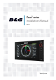
Zeus2 series Installation Manual ENGLISH bandg.
Preface As Navico is continuously improving this product, we retain the right to make changes to the product at any time which may not be reflected in this version of the manual. Please contact your nearest distributor if you require any further assistance. It is the owner’s sole responsibility to install and use the instrument and transducers in a manner that will not cause accidents, personal injury or property damage. The user of this product is solely responsible for observing safe boating practices.
user is encouraged to try to correct the interference by one or more of the following measures: Reorient or relocate the receiving antenna • Increase the separation between the equipment and receiver • Connect the equipment into an outlet on a circuit different from that of the receiver • Consult the dealer or an experienced technician for help Trademarks • • • NMEA 2000 is a registered trademark of the National Marine Electronics Association Navionics is a registered trademark of Navionics SpA B&G, Lowra
Contents 1 Zeus2 overview 2 3 Front - controls Rear - connections 4 Hardware installation 4 5 Display mounting location Display installation 7 Wiring 7 7 8 9 10 11 12 13 13 Guidelines Power connection Power Control connection External alarm Connect an external monitor NMEA 2000 – connection to backbone NMEA 0183 device connection Ethernet device connection Video in 14 Software setup 14 15 15 15 16 16 17 17 17 19 20 26 28 29 30 31 32 First time startup Time and Date Power Control setup Source
Zeus2 overview The Zeus2 range of multifunction displays consist of rugged marine displays with built in powerful marine processors. Display size choices are 7”, 9”, and 12” . All models come with a built in 10 Hz high gain GPS antenna. The ability to network over NMEA 2000 and ethernet allows access to data as well as control of numerous optional devices that can provide radar, audio entertainment, weather and even digital switching. All displays can operate on 12 V or 24 V systems.
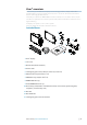
Front - controls ZEUS2 9/12 ZEUS2 7 2 1 3 4 5 6 7 8 1 Touch screen - cursor control, chart panning and zoom, context related menus 2 Home key - opens home page for page selection and setup options 3 Rotary knob - zooming and menu scrolling / selection by press 4 Exit - exits menu dialogue, clears cursor from screen 5 STBY/AUTO - autopilot control 6 Mark - places waypoint at vessel location 7 Power - turns on unit, opens System Controls dialogue, long press turns off 8 Card reader door - access to dual
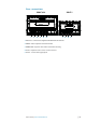
Rear - connections ZEUS2 9/12 1 1 2 3 4 ZEUS2 7 5 1 3 4 5 1 Ethernet - connection to high bandwidth network modules 2 HDMI - video output for external monitor 3 NMEA 2000 - dynamic data and user database sharing 4 Video - input for video sources such as cameras 5 Power - 12 V or 24 V supply input Zeus2 overview | Zeus2 Installation Manual |3
Hardware installation Display mounting location Choose the mounting locations carefully before you drill or cut; The display should be mounted so that the operator can easily use the controls and clearly see the display screen. B&G displays are high-contrast and anti-reflective, and are viewable in direct sunlight, but for best results install the display out of direct sunlight. The chosen location should have minimal glare from windows or bright objects.
Display installation Bracket mounting Place the bracket in the desired mounting location, and use a pencil or permanent marker to mark drilling locations. Note: ensure that the chosen location has enough height to accomodate the display fitted in the bracket, and allows tilting of the display. Also adequate space is required on both sides to allow tightening and loosening of the knobs. Use fasteners suited to the mounting surface material.
Flush mounting 1 2 X4 3 5 .0 mm .5 186 mm (7.8 .0 7") mm (7.5 (7.38") 192 7 2") M M REM OVE SHA DED ari *9 ARE 88 A O1 ne -1 DO NO NO TE : PR T SC INT AL 1:1 E M 6 on ito IMPO by RTAN copy from ing T. Do scale a le, or not prin use befo pleas ng. this re IMPO use.e checIf this temp impr RTAN k the is late originimé T.
Wiring Guidelines Care must be taken when running cables in a boat, to ensure that the cables are protected from damage and do not interfer with mechanical systems such as throttle cables and hatch covers. At each end of a cable, it is advisable to leave a short loop hanging lower than the termination point. This prevents any water that may get in contact with the cable from running down it to termination points vulnerable to corrosion.
Power Control connection The yellow Power Control wire on the Zeus2 power cable can either be an input that will turn on the processor when power is applied, or an output that turns on other devices when the processor is powered on. It can be configured at the installation stage to control the power state of displays and compatible devices. When commissioning the system, the Zeus2 can be set to be a Power Control Slave or Power Control Master.
Power Control master/slave bus Turning on the ‘master’ device turns on connected ‘slave’ devices. 1 2 3 4 5 6 7 + _ 8 1 Zeus2 displays 2 Power cable 3 Radar Interface box 4 Sonic Hub 5 Ground wire 6 Positive wire 7 Power control wire If the left Zeus2 turns on using the power button and is set as the Power Control Master, it will output voltage on the Power Control bus to power on the other Zeus2, the Radar Interface, and the SonicHub.
+ _ For sirens that draw more than 1 Amp, use a relay + _ Connect an external monitor The Zeus2 12 offers an HDMI output which can be connected to an external monitor to replicate video at a remote location. 1 3 2 4 1 MO series monitor 2 HDMI cable 3 Zeus2 12 4 HDMI cable - waterproof connector (use in exposed installations) Note: If connected to an HDTV it is possible the image may appear cropped, ie missing some detail at the outer edges of the screen.
NMEA 2000 – connection to backbone Device connection The Zeus2 multi function displays are equiped with an NMEA 2000 data port, which allows the receiving and sharing of a multitude of data from various sources. Essential network information • • • • • The standardised physical cables/connectors for NMEA 2000 are ‘Micro-C’ and ‘Mini-C’, directly derived from the automation industy’s ‘DeviceNET’ - ‘Micro-C’ being the more commonly used size.
The following drawing demonstrates a typical small network. The backbone is made up of direcly interconnected T-piece joiners and an extension cable, which is terminated at each end.
multiple receivers (Listeners). The number of receivers is finite, and depends largely on the receiving hardware. Typically driving three devices is possible. Ethernet device connection Ethernet is used to interconnect high bandwidth devices such as radar, sonar, and other multi function displays. The Zeus2 7/9 have one ethernet port, whereas the Zeus2 12 has two. Connection of network devices can be made directly, or via a NEP-2 ethernet expansion port.
Software setup The Zeus2 requires some initial configuration before use, in order to get the most out of the product. The following sections focus on settings that typically will not require change once configured. User preference settings and operation are covered in the operator manual. Pressing the home key brings up the home page, which has three distinct panels.
Time and Date Configure time settings to suit vessel location. Power Control setup Determines unit response to signal applied to yellow wire of power cable. These settings do not require adjustment if the yellow wire is connected to ignition or to a stand-alone switch that applies 12V/24V. Note: The System Controls menu will not display the ‘Power Off’ option when unit is configured as slave. To power down device, the master device must be powered down, or system power removed.
Group source selection B&G multifunction displays, autopilot controllers, and instruments have the ability to; • use data sources (eg position, wind direction, etc) that all other products on the network use, or alternatively use a data source independently from other units. • globally change all displays over to a different source from any display. (This will only include products set to Group mode.) In order to enable group selection, the display must be set to ‘Default’ group.
Diagnostics The NMEA 2000 tab on the diagnostics page can provide information useful for identifying an issue with the network. Bus state simply indicates whether the bus is powered, but not necessarily connected to any data sources. However if bus shows as ‘off ’, but power is present along with an increasing error count, it is possible that termination or cable topology is incorrect. Rx Overflows: The CAN driver got too many messages for its buffer before the application could read them.
Scanner type Identifies the model of scanner connected to the network. Software version Check to make sure you have the latest software. check website for the latest version. Serial Number This number should be recorded for support and insurance purposes. MARPA status The MARPA status can identify if a heading sensor is on the network and that the radar is receiving heading information essential for MARPA calculations. Reset device ID The earlier Zeus models only support one radar on the network.
• • control until the sidelobe returns are just eliminated. You may need to monitor 5-10 radar sweeps to be sure they have been eliminated. Traverse the area again and readjust if sidelobes returns still occur. Exit the installation menu. Restore radar to Factory Default This can be used to revert all user adjustments. Video In configuration Press the menu key when on the video page or panel to open the setup dialogue. Enable PAL or NTSC depending on the video ouput standard of the selected camera.
Autopilot setup Verifying the autopilot connection When an AC12N, AC42N, or SG05 is connected to the Zeus2 system, the Zeus2 will automatically detect the autopilot and an Autopilot menu icon will be included in the ‘Settings’ menu. If no ‘Autopilot’ icon is available in the menu, establish the connection by running the auto select process.
5. • 6. Set the drive voltage Refer to the drive unit table in the AC12N/AC42N Installation manual or to your drive unit documentation for information. Run the rudder test as described in the on-screen instructions Note: If the boat uses power assisted steering, it is important that the engine or electric motor used to enable the power assist steering is turned on prior to this test.
rudder from continuous hunting. A deadband will cause inaccurate steering. Note: The rudder deadband setting is not available when the autopilot is configured for Virtual Rudder Feedback. Seatrials A seatrial can only be performed if the dockside settings are completed and confirmed. The seatrial must always be performed in open waters at a safe distance from other traffic.
Setting the Transition speed (HI/LO) This is the speed at which the system automatically changes from LO to HI steering parameters. On power boats it is recommended that you set a value that represents the speed where the hull begins to plane or the speed where you change from slow to cruising speed. On sailboats the transition speed should be set to around 3-4 knots to give the best response in a tack.
Setting sailing parameters Note: Sailing parameter settings are only available if the boat type is set to Sail. Tack time When performing a tack in WIND mode, the rate of turn (tack time) can be adjusted. This will give single-handed sailors time to handle the boat and the sails during a tack. A turn performed without shifting wind side, will also be made at a controlled turn rate.
1 2 3 1 Counter rudder too low; overshoot response 2 Counter rudder too high; sluggish and creeping response 3 Correct setting or counter rudder; ideal response Auto trim This parameter defines how fast the autopilot shall correspond after having registered a heading error. The standard value is 40 seconds which should work well on most boats. Rule of thumb: Set to same value (seconds) as the boat’s length in feet. On boats operating on VRF the value should be set to 20 seconds.
Fuel setup The fuel utility monitors a vessels fuel consumption. This information is totalled to indicate trip and seasonal fuel usage, and is used to calculate fuel economy for display on instrument pages and the data bar. To use the utility, a Navico Fuel Flow sensor (petrol/gasoline only), or a NMEA 2000 engine adaptor cable/gateway with Navico Fuel Data Storage device must be fitted to the vessel.
3. 4. 5. Select the ‘Calibrate’ option. Set the ‘actual amount used’ based on amount of fuel added to tank. Select OK to save settings. The ‘Fuel K-Value’ should now show a new value. Note: To calibrate multiple engines repeat the steps above, one engine at a time. Alternatively, run all engine simultaneously, and divide the ‘Actual amount used’ by the number of engines. This assumes reasonably even fuel consumption on all engines.
CZone setup In order to communicate with the CZone modules connected to the network, the Zeus2 must be assigned a unique CZone Display Dipswitch setting. The functionality of the CZone system is determined by the CZone Config File (.zcf ), which is stored on all CZone modules and supported B&G displays, such as the Zeus2. The file is created using the CZone Configuration Tool, a specialised PC application available from BEP Marine Ltd, and associated CZone distributors.
Software updates and data backup From time to time B&G releases software updates to its existing products. Updates are created for a variety of reasons; to add or improve features, to add support for new external devices, or to fix software bugs. Updates can be found on the B&G website: http://www.bandg.com/Support/Downloads/ The Zeus2 may be used to apply software updates to itself, and to supported NMEA 2000 and ethernet devices, with files read off an SD card.
NMEA 0183 setup The NMEA 0183 port must be set to suit the speed of connected devices, and can be be configured to output only the sentences required by listening devices. Receive waypoint Select this option to allow device capable of creating and exporting waypoints via NMEA 0183 to transfer directly to the Zeus2. Baud rate This should be set to correspond with devices connected to the NMEA 0183 input and output. The input and output (Tx, Rx) use the same baud rate setting.
Ethernet setup No special setup is required for establishing an ethernet network, it is all ‘plug and play’ . An NEP-2 connected between an Zeus2 and another network module (e.g. 4G radar) will automatically start working, and relay data between the two devices. Diagnostics The UDB (User Data Base) tab on the diagnostics page, provides information on Ethernet activity, as shown below. The ‘Reset Display List’ can be used to refresh the list of connected displays and their UDB version.
Wifi setup To connect to a GoFree device a suitable wifi Android tablet or Apple ipad is required. Navigate to the wifi network connection page on the tablet, and find the ‘GoFree Wifi xxxx’ network. Connect to the network using the eight character password printed on the silver label of the GoFree module. If the module is installed out of easy access, see the following section ‘Access Points’ on how to identify the ‘Network Key’ (password) from the Zeus2.
Channel Channel setting is available in order to overcome potential interference to the GoFree device by another RF device transmitting in the same frequency band. Advanced Tools are available within the Zeus2 software to assist in fault-finding and setting up the wifi network. Iperf Iperf is a commonly used network performance tool. It’s provided for testing Wifi network performance around the vessel so weak spots or problem areas can be identified.
Accessories Part number 000-11586-001 000-11587-001 000-11588-001 000-11589-001 000-11591-001 000-11593-001 000-11595-001 000-11598-001 000-11599-001 000-11600-001 34 | Description Zeus2 LITERATURE PACK Zeus2 CHART CARD DOOR Zeus2 CONNECTOR COVERS (7/9”) Zeus2 CONNECTOR COVERS (12”) Zeus2 7 SUN COVER Zeus2 9 SUN COVER Zeus2 12 SUN COVER Zeus2 7 EDGE BEZELS (PAIR - SILVER AND BLACK) Zeus2 9 EDGE BEZELS (PAIR - SILVER AND BLACK) Zeus2 12 EDGE BEZELS (PAIR - SILVER AND BLACK) Accessories | Zeus2 Installatio
Supported data NMEA 2000 compliant PGN List NMEA 2000 PGN (receive) 59392 59904 60928 61184 65285 65289 65291 65292 65293 65323 65325 65341 65480 126208 126992 126996 127237 127245 127250 127251 127257 127258 127488 127489 127493 127503 127504 127505 127506 127507 127508 127509 128259 128267 128275 129025 129026 129029 129033 129038 129039 129040 129283 129284 129539 ISO Acknowledgement ISO Request ISO Address Claim Parameter Request/Command Temperature with Instance Trim Tab Insect Configuration Backlight
129540 129794 129801 129802 129808 129809 129810 130074 130306 130310 130311 130312 130313 130314 130576 130577 130840 130842 130845 130850 130851 130817 130820 130831 130832 130834 130835 130838 130839 130843 36 | GNSS Sats in View AIS Class A Static and Voyage Related Data AIS Addressed Safety Related Message AIS Safety Related Broadcast Message DSC Call Information AIS Class B “CS” Static Data Report, Part A AIS Class B “CS” Static Data Report, Part B Route and WP Service - WP List - WP Name & Position
NMEA 2000 PGN (transmit) 61184 65287 65289 65290 65291 65292 65293 126208 126992 126996 127237 127250 127258 128259 128267 128275 129025 129026 129029 129283 129284 129285 129539 129540 130074 130306 130310 130311 130312 130577 130840 130845 130850 130818 130819 130828 130831 130835 130836 130837 130839 130845 130850 Parameter Request/Command Configure Temperature Insects Trim Tab Insect Calibration Paddle Wheel Speed Configuration Backlight Control Clear Fluid Level Warnings LGC-2000 Configuration ISO Com
NMEA 0183 supported sentences TX / RX GPS Receive GGA GLL GSA GSV VTG ZDA Transmit GGA GLL GSA GSV VTG ZDA APB BOD BWC BWR RMC DBT DPT MTW VLW VHW DBT DPT MTW VLW VHW HDT HDM Navigation Receive RMC Transmit AAM RMB XTE Echo Receive Transmit Compass Receive HDG Transmit HDG Wind Receive MWV MWD Transmit MWV MWD AIS / DSC Receive DSC DSE VDM AIS sentences are not bridged to or from NMEA 2000.
Specifications Mechanical/Environmental Model Casing Operating temp Water ingress Weight (exluding mounting hardware) Display brightness Display resolution Viewing angle in degrees (typical value @ contrast ratio =10) Dimensions (overall) Electrical Model Operating voltage Power consumption Low power standby mode Protection Alarm output current Processor Conformity Interfaces Model Ethernet NMEA 2000 (compliant) Video input Video output SD NMEA 0183 port baud rate Charting support Specifications | Zeus2 In
Dimensioned drawings Zeus2 7 and Zeus2 9 ZEUS2 7: 163.6mm (6.44”), ZEUS2 9: 178.27mm ZEUS2 7: 147.2mm (5.8”), ZEUS2 9 163.6mm (6.44”) ZEUS2 7: 231.5mm (9.11”), ZEUS2 9: 279.4mm (11”) ZEUS2 7: 251.1mm (9.89”), ZEUS2 9: 305.1mm (12.0”) ZEUS2 7: 105.6mm (4.16”) ZEUS2 9: 106.6mm (4.20”) ZEUS2 7: 84.0mm (3.31”) ZEUS2 9: 84.0mm (3.30”) ZEUS2 7: 122mm (4.8”) ZEUS2 9: 147.1mm (5.79”) Zeus2 12 105.6mm (4.16") 375.1mm (14.77") 40 | 84.0mm (3.3") 249.5mm (9.82") 215.0mm (8.46") 345.0mm, (13.
0980 *988-10604-001*