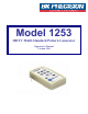
Model 1253 HDTV Multi-Standard Pattern Generator Operator's Manual Version 3.
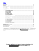
Index Introduction _________________________________________________________________ Operation _________________________________________________________________ Connecting the Unit ___________________________________________________________ Power Supply ___________________________________________________________ Low Battery Alarm ___________________________________________________________ 2 3 5 5 5 PATTERNS* _________________________________________________________________ 1: SMPTE Bars Pattern __________
Introduction Thank you for purchasing the BK-1253, the affordable HDTV-Component test-pattern-generator, designed to be a useful tool for the new generation of DTV (Digital TV) products. During the year 2001, over 1.1 million DTV units were shipped, exceeding expectations of the industry. This trend should continue to grow, especially that the FCC has mandated the existence of DTV. Presently 95.8% of U.S. can receive HDTV broadcasts.
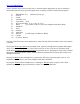
OPERATION: The POWER Switch This Power Switch, on the right side of the unit, turns the power to the unit on and off. Slide the switch the upward position to turn the unit on. The red POWER LED will be on. Slide the switch the downward position to turn the unit off. The red POWER LED will be off.
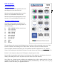
The PATTERN Buttons These 14 buttons may be pressed at any time, to select the Pattern displayed as an icon on the button. Some Pattern buttons may be pressed multiple times, to display variations of that particular pattern. 1) 2) 3) 4) 5) 6) 7) 8) 9) 10) 11) 12) 13) 14) SMPTE Bars 75% (default on power-up) PLUGE Needle Color Bars 75% Cross Hatch [16:9] DVD Aspect Ratio [1.33, 1.78, 1.85, 2.
Connecting the unit There are 3 BNC connectors on the top of the unit, labeled Y, Pb and Pr. These are HDTV-Component video connections to be connected to the Y, Pb and Pr connectors of a HDTV monitor or TV with component video input. There is also a DIN connector, labeled S-VID. This is a S-Video (S-VHS) video connector to be connected to a TV with a S-VID input.
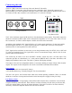
Patterns 1: SMPTE Bars (Society of Motion Pictures and Television Engineers) Description: 7 equal width vertical bars in 3 groups. The top 2/3 of the pattern contains White (R+G+B), Yellow (R+G), Cyan (G+B), Green (G), Magenta (R+B), Red (R), and Blue (B) bars, from left to right, at 75% (100% saturation).
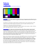
There are various other applications for SMPTE Bars. It has value in VTR testing and in quick checks of the system phasing thru monitors and Vectorscopes. Vectorscope Display of SMPTE Bars SMPTE Bars are also often used for Tape Headers, or sometimes between edit cuts. Also often used for testing transmission equipment. Examples of Uncalibrated Displays: The following images indicate a TV with incorrect hue settings. Adjust the Hue (or Tint) setting so the first bar appears white (or gray).
2: PLUGE (Picture Line Up Generator Equipment) Description: The Pluge pattern (Picture Line-Up Generator Equipment – BBC development) is arranged in four concentric rectangular zones. The innermost rectangle is fixed at black (7.5 IRE for NTSC, 0 IRE for other formats) and has a five-step gray scale positioned on it. The second rectangular zone from the center alternates between two light levels, black and slightly blacker than black (7.5/0 IRE for NTSC, 0/-5 IRE for other formats).
3: Needle Description: This pattern is black on the top half and white on bottom half, with lines (needle pulses) drawn from top to bottom on each side of the pattern, through the black/white transition. Electrically, the needle pulse lines are the same width on the top and the bottom of the pattern. Pattern Usage: This pattern makes it easy to detect whether scan velocity modulation (SVM) is enabled on a display device.
4: Color Bars Color Bars 75% Same as the top of the SMPTE Bars Pattern Description: Seven equal-width vertical bars with 75% (gray) at left, followed by three primary and three secondary colors. Color bars are at 100% saturation with 75% amplitude. Pattern Usage: Use as an overall check of a display device’s capability of producing fully saturated primary and secondary colors. Especially helpful in detecting full (or partial) loss of colors in older displays.
5: Cross Hatch Description: A grid of 16 x 9 boxes, separated by white lines. Pattern Usage: Used to check and adjust convergence of red, green and blue pictures. The horizontal and vertical lines are usually best observed to detect color fringing resulting from misconvergence, and the dots are usually best observed to make fine adjustments.
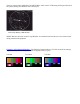
6: DVD Aspect Ratio Description: Grayscale rectangles occupying a user selected aspect ratio, on top of a black background. The outer rectangle is at 75% gray, with an inner rectangle at 50% (mid) gray. The border of the outer rectangle occupies 10% of the width and height of the rectangles. Through the center of this border is a black line at 5%. This simulates the output of a DVD player generating an image area displayed by the rectangles.
DVD Aspect Ratios as seen on TVs and Monitors These images show how different aspect ratios will appear on SDTV (4:3) and HDTV (16:9) monitors. SDTV 4:3 Monitor Aspect Ratio: 1.33 : 1 1.78 : 1 1.85 : 1 2.
7: Raster Description: Full field color raster patterns at 75% amplitude. Variations: Pressing The Raster button multiple times, sequences the full-screen output through 8 colors, at 75% amplitude: White, Yellow, Cyan, Green, Magenta, Red, Blue, and Black. Pattern Usage: Use to check color purity and display chrominance uniformity.
8: Multiburst Description: Consists of 6 frequency bands increasing in frequency, from left to right, and separated by gaps of mid gray. Vertical segments are filled with alternating black and white stripes. The frequencies are at 1.125MHz, 2.25MHz, 3.375MHz, 4.5MHz, 6.75MHz and 13.5MHz for the HDTV formats, and 0.75MHz, 1.125MHz, 2.25MHz, 3.375MHz, 4.5MHz and 6.75MHz for the SDTV formats.
9: Focus BK BK BK BK BK BK BK BK BK BK BK BK BK BK BK BK BK BK BK BK BK BK BK BK BK BK BK BK BK BK BK BK BK BK BK BK BK BK BK BK BK BK BK BK BK BK BK BK BK BK BK BK BK BK BK BK BK BK BK BK BK BK BK BK BK BK BK BK BK BK BK BK BK BK BK BK BK BK BK BK BK BK BK BK BK BK BK BK BK BK BK BK BK BK BK BK BK BK BK BK BK BK BK BK BK BK BK BK BK BK BK BK BK BK BK BK BK BK BK BK BK BK BK BK Description: Consists of capita
10: Staircase Description: 11 equal-width vertical bars step from black at 0 IRE (7.5 IRE for NTSC) on the left, to 100 IRE (white) on the right. Pattern Usage: Useful for visually checking gray-scale tracking performance of a display. Poor performance is seen as a primary color tint (red, green, or blue), especially at the bright or dark end of the pattern. Also useful for adjusting gray-scale tracking by eye, when a color analyzer is not available.
11: ANSI Gray Description: Pattern is an all white raster with two centered three-step gray scales. The top gray scale steps are at 10%, 5%, and 0% white levels. The bottom gray scale steps are at 90%, 95%, and 100% white levels (from left to right). Pattern Usage: This pattern can be used to check a display device’s ability to hold proper black level at close to 100% APL. Check that you can see three separate levels of dark gray and black in the top gray scale.
12: Window This PLUGE Bar is the only bar which should be visible Description: Centered 1/3 white window on black background. Luminance levels of Window are independently adjustable from 0 IRE to 100 IRE in 2.5 IRE steps. The window pattern includes PLUGE level bars at +5% and –5% of black to the left of the white window. Variations: Pressing The Window button multiple times, or holding the Window button, sequences the window Luminance Level from black to white, then white to black.
13: Checker Description: Alternating picture areas of black and white in a checkerboard pattern. Pattern Usage: Checks the regulation of CRT video drive power supply circuits. The pattern produces abrupt, maximum changes in CRT video drive current. Ideally, this should not cause the voltage supplied to the video drive circuits to change (good voltage regulation). If the power supply does not have good regulation, it will cause softening or ringing of the vertical line pattern transitions.
14: Overscan-Bounce (Regulate) Description: Sometimes called "Regulate", this pattern consists or 4 horizontal and vertical lines at the edges of the screen, marking 2.5%, 5%, 7.5% and 10% of the width and height of the screen. The center of the screen flashes between full white and black every 1 1/3 seconds. Pattern Usage: Used to test the amount of overscan of a monitor (usually a CRT type), and to check the regulation of a CRT monitor's high-voltage and deflection power supply circuits.
Specifications: Number of Video Formats 12: 1: 1920x1080 30i 2: 1920x1080 30p 3: 1920x1080 24p 4: 1280x720 60p 5: 1280x720 30p 6: 1280x720 24p 7: 704x480 60p 8: 704x480 30p 9: 704x480 30i 10: NTSC 11: PAL 12: SECAM Number of Patterns 14: 1: SMPTE Bars 75% 2: PLUGE 3: Needle 4: Color Bars 75% 5: Cross Hatch [16:9] 6: DVD Aspect Ratio [1.33, 1.78, 1.85, 2.35] 7: Raster [75% wht, yel, cyn, grn, mag, red, blu, blk] 8: Multiburst 9: Focus 10: Staircase 11: ANSI Gray 12: Window [2.
Display Calibration Important Notes: The information in this document describes how the BK Precision BK-1253 HDTV Test Pattern Generator may be used to calibrate and verify the performance of HDTV display products. This information is applicable only to the BK Precision BK-1253. 1. Black-level (Brightness) Calibration Correct black-level calibration is critical to achieving a picture with full contrast and subtle details in dark shadow regions.
Black-level Calibration Procedure: Black-level should be adjusted at the beginning of a complete display calibration. It must also be monitored and readjusted during the display calibration process. The Black-level adjustment often interacts with the Contrast adjustment and will change during the Color Temperature and Grayscale Tracking adjustments. The BK-1253 provides unique calibration patterns to monitor and re-adjust black-level while making those adjustments.
than is a full screen measurement. Most fixed-pixel projection systems produce the same brightness in full fields as small areas because they have fixed brightness sources provided by projection bulbs. BK-1253 Contrast Adjustment Patterns: The BK-1253 has several patterns that can be used together to determine the best operating point for the Contrast control. These include the Window, Multiburst, PLUGE, Needle, Overscan-Bounce , and Grey Raster patterns.
Short-term high-voltage stability problems may be evident on the inner horizontal staircase of the PLUGE pattern. Look for trapezoidal distortion of the lighter rectangles. The Needle Pulse pattern is a more sensitive indicator of short-term stability problems. The upper half of the pattern is black with narrow white vertical lines on both sides. The bottom half of the pattern is reversed.
3. Geometry Calibration Geometry calibration is the process of adjusting the display for the correct picture size, while ensuring that horizontal and vertical lines in the picture remain straight and parallel to the edges of the picture and evenly spaced from one another when using an appropriate calibration pattern. Displays may have an array of adjustments for this purpose including horizontal and vertical position, size, linearity, tilt, bow, keystone, pincushion and others.
4. Convergence Calibration Convergence calibration is the process of aligning the separate red, green and blue CRT beams in direct-view monitors, or the projected red, green and blue images from separate CRTs in projection systems, so that they precisely overlap everywhere in the picture. This is particularly crucial in HDTV displays in order to maximize resolution and avoid color fringing on fine lines or edges in the picture.
5. Color Temperature and Grayscale Calibration Accurate color depends on calibrating the display for the proper grayscale color temperature of 6500 degrees Kelvin, which is called D65 or D6500. The color temperature must remain constant over the entire range of the grayscale from near black to peak-white (100 IRE). It is somewhat ironic that accurate color is dependent on accurate shades of gray. If the color temperature of gray is too high, the picture will have a blue tint.
A good initial procedure is to adjust the Bias controls for D65 using the 25 IRE Grayscale Window pattern and then adjust the Gain controls for D65 using the 75 IRE Grayscale Window. The adjustments will interact and it will be necessary to move back and forth between the calibration patterns several times before both patterns can be set to D65. Use the PLUGE stripes at the left side of the Window patterns to ensure that the Black-level remains set correctly, especially when adjusting the Bias controls.
6. Color Saturation & Hue Calibration HDTV displays with YPbPr component video inputs include a Color saturation control. This changes the amplitude of the Pb and Pr (color-difference) signals with respect to the Y (luminance) signal, which affects the sensation of color depth or vividness of color. Deep colors are highly saturated and pastel colors, or shades of white, have minimum color saturation. A few displays may also provide a Hue control that adjusts the shade of the colors.
7. Sharpness/Detail Enhancement Calibration If the display includes Sharpness or Detail Enhancement controls they should be calibrated to maximize apparent picture resolution, but avoid any excessive edge-enhancement that creates outlining artifacts.
8. Other Performance Checks A Checkerboard pattern with black and white squares is included for measuring the amount of light leakage in the black areas of the picture. There are 36 rectangular (16:9 or 4:3) blocks in a 6x6 pattern. The black blocks are at 0 IRE (7.5 IRE for NTSC) and the white blocks are at 100 IRE. You can also use this pattern to make simple contrastratio measurements in different areas of the display.
Limited One-Year Warranty B&K Precision Corp. warrants to the original purchaser that its product and the component parts thereof, will be free from defects in workmanship and materials for a period of one year from the data of purchase. B&K Precision Corp. will, without charge, repair or replace, at its’ option, defective product or component parts. Returned product must be accompanied by proof of the purchase date in the form a sales receipt. To obtain warranty coverage in the U.S.A.
Service Information Warranty Service: Please return the product in the original packaging with proof of purchase to the below address. Clearly state in writing the performance problem and return any leads, connectors and accessories that you are using with the device. Non-Warranty Service: Return the product in the original packaging to the below address. Clearly state in writing the performance problem and return any leads, connectors and accessories that you are using with the device.
SN: 481-419-9-001 Printed in USA 2003 B&K Precision Corporation 22820 Savi Ranch Parkway Yorba Linda, CA 92887 USA TEL: 714-921-9095 FAX: 714-921-6422