Model 1685B, 1687B, 1688B Switching DC Power Supply INSTRUCTION MANUAL
1 Safety Summary The following safety precautions apply to both operating and maintenance personnel and must be observed during all phases of operation, service, and repair of this instrument. Before applying power, follow the installation instructions and become familiar with the operating instructions for this instrument. GROUND THE INSTRUMENT To minimize shock hazard, the instrument chassis and cabinet must be connected to an electrical ground.
WARNINGS AND CAUTIONS WARNING and CAUTION statements, such as the following examples, denote a hazard and appear throughout this manual. Follow all instructions contained in these statements. A WARNING statement calls attention to an operating procedure, practice, or condition, which, if not followed correctly, could result in injury or death to personnel.
Compliance Statements Disposal of Old Electrical & Electronic Equipment (Applicable in the European Union and other European countries with separate collection systems) This product is subject to Directive 2002/96/EC of the European Parliament and the Council of the European Union on waste electrical and electronic equipment (WEEE), and in jurisdictions adopting that Directive, is marked as being put on the market after August 13, 2005, and should not be disposed of as unsorted municipal waste.
Contents 1 Safety Summary ........................................................................................ 1 2 Introduction .............................................................................................. 6 3 Controls and Indicators ............................................................................. 7 4 3.1 Front Panel ........................................................................................ 7 3.2 Rear Panel ...........................................
5.1.2 Using Two 5 kΩ Variable Resistors.......................................... 19 5.1.3 Enable and Disable the Output ............................................... 20 5.2 6 PC Interface Control ........................................................................ 21 5.2.1 General Functions and Display................................................ 21 5.2.2 External Timed Program ......................................................... 22 5.2.3 Internal Preset Memory ...................
2 Introduction B&K Precision models 1685B, 1687B, and 1688B are laboratory grade switching mode DC power supplies with high current output in a small form factor and lightweight package. The 1685B Series provides various configurations of output voltage and current, and make setting voltage and current levels fast and precise through its dual action, coarse/fine rotary encoder control knobs.
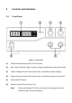
3 Controls and Indicators 3.1 Front Panel Figure 1 - Front Panel (1) LED panel meter display with CV/CC indicator (2) Rear Control Indicator (lights up when using Preset/Remote Control/Set mode) (3) Output Voltage Control Knob (control main and auxiliary output voltage) (4) Output Current Control Knob (control main and auxiliary output current limit) (5) Power ON/OFF Switch (6) Auxiliary Output Terminal (max 5 A) Note: Please see Section 4.1.
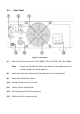
3.2 Rear Panel Figure 2 - Rear Panel (7) Main Output Terminal (max 5 A for 1685B / 10 A for 1687B / 20 A for 1688B) Note: Please see Section 4.1.4 for more details on using both main and auxiliary output terminals together.
4 Operating Instructions Safety Precautions ● This power supply is for indoor use only. ● Do not expose the power supply to sun, high humidity, or dusty environments. ● Never remove the metal cover of the power supply while AC power is connected. ● Never touch the unit when your hands are wet. ● Never block the ventilation slots and cooling fan air intake window. ● Never attempt to repair the power supply. Incorrect re-assembly may result in a risk of electric shock or fire.
4.1 Using the Power Supply 4.1.1 Connection To connect the equipment to the power supply, follow the steps below. 1. Check the rating label of the power supply and confirm that it complies with your AC mains voltage. 2. Connect the power supply to the AC mains using the provided power cord and make sure the Mode Selection Switch is in the Normal position. 3.
Front Panel Display Test Segment check C.V. indicator check C.C. indicator check Rear control indicator check Return to C.V.
Front Panel Display Test Overtemperature protection check Fan check Output off (remote control mode) Table 2 - Self Test Sequence The LED and other indicators on the front panel will be turned on. When the cooling fan is being checked, a loud fan noise can be heard. After the self checks, the CV, V, and A LED indicators are lit up displaying voltage and 0.0 current. To find out about the set CC current level, just turn the current control knob one click in either direction.
4.1.4 Using Both Main and Auxiliary Outputs The power supply has a main output in the rear and an auxiliary output in the front that can be used separately or together. The main and auxiliary output both share the same voltage and current control knobs and will output the same voltage and current up to the maximum output ratings of the power supply and terminals.
Note: 4.2.1 The power supply is factory preset to Normal Mode with maximum current level. Normal Mode This is the factory preset mode and the power supply output voltage and current are controlled by the dual action dial knobs. Push the knobs to toggle the coarse and fine tuning. You will notice the subtle change in brightness of LED. Adjust the knobs to your desired values through coarse and fine tuning. To check the preset current level, turn the Current Knob lightly in any direction.
4.2.3 Set Mode First, enter Set Mode by pushing Mode Selection Switch to “Set” position. To define the preset output P1/P2/P3 1. Select the Recall Switch to the position you want to set: P1, P2, or P3. 2. Adjust the front panel voltage control knob to set your desired voltage value. 3. Adjust the front panel current control knob to set your desired current limit value. 4. Repeat the procedure for remaining presets P1, P2, or P3 if desired. 5.
4.2.4 Analog Remote Control Mode Select this mode to control the output voltage and current via remote control connector. Please refer to Section 5.1 for more details. 5 Remote Control There are two methods to remotely control voltage and current. Note: Both methods require the remote control connector plug to be set up in order for analog remote control mode to be functional; otherwise the unit will be in CC mode all the time. 5.1 Analog Remote Control Set up the provided remote connector plug.
Figure 4 - Pin Numbers (c) Make sure the load is disconnected and the power supply is OFF. (d) Plug the remote connector plug into the analog remote control terminal of the power supply. (e) Secure the remote connector plug to the terminal socket by screwing in the connector ring (Figure 5).
5.1.1 Using Two External Variable DC Voltage Sources PIN FUNCTIONS REMARKS 1 Internal DC +5 V Less than 50 mA 2 Voltage Adjust 0–5V 3 Current Adjust 0–5V 4 Ground 5 Output OFF 6 N/A 7 N/A 8 N/A Short to Ground Table 4 – Remote Connector Plug Pin Assignment for External Variable Voltage Sources A variable external DC voltage source of 0 – 5 V is fed into the analog remote control terminal to adjust the output voltage level of both Main and Auxiliary output.
5. Switch on the power supply. 6. Check the output voltage range of the power supply by varying the external voltage source for voltage adjustment from 0 to 5 V. 7. Short circuit the main output with an 8AWG gauge wire and check the display for CC setting by varying the external voltage source for current adjustment from 0 to 5 V. 8. Switch off the power supply. 5.1.2 Using Two 5 kΩ Variable Resistors 1. Make sure the load is disconnected and the power supply is OFF. 2.
PIN FUNCTIONS REMARKS 1 Internal DC +5 V Resistor end 2 Voltage Adjust Variable part of resistor 3 Current Adjust Variable part of resistor 4 Ground Resistor end 5 Output OFF Short to Ground 6 N/A 7 N/A 8 N/A Table 5 – Remote Connector Plug Pin Assignment for Variable Resistors 3. Turn the remote control ON/OFF switch to ON position. 4. Switch on the power supply. 5. Check the output voltage range of the power supply by varying the 5 kΩ variable resistor for voltage adjustment. 6.
Shorting Pin 5 to Pin 4 (ground) will turn the output off. When output is off, the CV and CC LED will flash. The current output voltage and current setting will show on the panel meter. You can also adjust the output by voltage and current control knob to your desired value when output is off. 5.2 PC Interface Control Note: The power supply must be in Normal Mode for PC interface control. 5.2.
5.2.2 External Timed Program External Timed Program is completely controlled by the PC. The PC counts the step time and changes the specified voltage and current levels of the power supply. Figure 8 - External Timed Program External Timed Program Procedure 1. Select External Timed Program tab to switch to the External Timed Program function. 2. Enter voltage, current, and time parameters for number of steps needed in timed program. (Maximum of 20 steps can be entered) 3.
5.2.3 Internal Preset Memory The Internal Preset Memory tab allows you to define the power supply’s presets remotely. Figure 9 - Internal Preset Memory Internal Preset Memory Procedure 1. Select Internal Preset Memory tab to switch to the Internal Preset Memory function. 2. Enter in desired Voltage and Current values for Presets 1, 2, and 3. 3. Click “Set” to select and save Presets. 4. To get power supply’s currently stored presets, click the “Read from PS” button. 5.
5.2.4 Data Log The Data Log window can be used to view present or stored output data. All parameters at the bottom of the window can be changed via direct entry from the PC and confirmed by pressing Enter or selecting the values from the drop down menu.
To save a data log, enter Log Name in box and click the “Save Log” icon. After saving, the log can be retrieved by selecting it in the Log Name drop down menu. Data logs can be classified, stored, exported to a csv file, printed, or retrieved for use at any time. THE TIME FRAME CONCEPT OF DATA LOG The data logging function starts when the software begins to run. When T Min is set to 0 seconds, it means the data is in real-time and the length of time lapsed is on the left hand side of the Time Minimum.
5.2.5 Settings Use this tab to configure your settings. Figure 12 - Settings Configuration Data Log Sampling Time: You can select your desired data log sampling time from 1 second and up. Voltage Upper Limit (UVL) Setting: You can set your output voltage upper limit value to safeguard your low voltage applications. Current Upper Limit (UCL) Setting: You can set your output current upper limit value to safeguard your low current applications. 5.2.
Command line format: COMMAND…[CR] Current value will have one decimal place for models 1687B and 1688B, and two decimal places for Model 1685B. Command code & Return value Function Example Input command: VOLT{}[CR] Set voltage level = 000-XXX Input command: VOLT010[CR] Return value: OK[CR] Return value: OK[CR] Sets voltage level to 1.
Command code & Return value Input command: GETD[CR] Function Example Get display voltage, current, and status reading from power supply Input command: GETD[CR] Return value: [voltage][current][stat us][CR] [voltage] = 0000-XXXX OK[CR] [current] = 0000-XXXX [status] = 0|1 (0=CV, 1=CC) Return value: 030201450 OK Input command: GETM[CR] Get preset memory values Input command: GETM[CR] Return value: [preset 1 voltage] [preset 1 current][CR] [preset 2 voltage][preset 2 current][CR] [preset 3 voltage][p
Command code & Return value Input command: SOUT{
Command code & Return value Function Example Input command: GOCP[CR] Get upper current limit of power supply Input command: GOCP[CR] Return value: [current][CR] OK[CR] [current] = 000-XXX Return value: 052 OK Indicates maximum current limit is set to 5.
6 Faults and Troubleshooting 6.1 OVP: Overvoltage Protection This unit has a built-in tracking overvoltage protection feature. In the event of the output voltage becoming greater than the set value (see specified range from Specifications section), protection will be triggered, and the output power will be cut off. OVP warning will appear as shown below. Figure 13 - Overvoltage Protection To reset the warning, switch off the unit and remove all connected devices.
Figure 14 - Overtemperature Protection When you get this warning, switch off the unit and remove all loading. Check your load and output settings and allow the unit to cool down for at least 30 minutes. Check if any of the ventilation is blocked and make sure there is enough clearance around the power supply. Listen carefully for the fan noise from the cooling fan when you turn on the unit again.
Figure 15 - Overload Protection To reset this warning, switch off the unit and remove all connected devices. Switch the unit back on again and double check with caution. If the problem persists, please contact B&K Precision. 6.4 Fuse Replacement If the fuse blows, the CV or CC indicators will not light and the power supply will not operate. The fuse should not normally open unless a problem has developed in the unit.
7 Specifications Models 1685B 1687B 1688B Variable Output Voltage 1 – 60 V 1 – 36 V 1 – 18 V Variable Output Current 0–5A 0 – 10 A 0 – 20 A Output Voltage Regulation Load (0-100% Load) ≤ 50 mV Line (90-132 VAC, 170-264 VAC Variation) ≤ 20 mV Current Regulation Load (10-90% Rated Voltage) ≤ 100 mA Line (90-132 VAC, 170-264 VAC Variation) ≤ 50 mA Ripple & Noise Ripple & Noise Voltage (rms) ≤ 5 mV Ripple & Noise Voltage (peak-peak) ≤ 50 mV Current Ripple & Noise (rms) ≤ 30 mA Meter
Models Tracking Overvoltage Protection 1685B 1687B O/P 1-5 V: set O/P 1-5 V: set voltage +2 V voltage +2 V O/P 5-20 V: set O/P 5-20 V: set voltage +3 V voltage +3 V O/P 20-60 V: set O/P 20-36 V: set voltage +4 V voltage +4 V Transient Response Time (50-100% Load) 1.5 ms Power Factor Correction > 0.
8 Certification CE Compliant CE Declaration of Conformity The power supply meets the requirements of 2006/95/EC Low Voltage Directive and 2004/108/EC Electromagnetic Compatibility Directive.
9 Service Information Warranty Service: Please go to the support and service section on our website at www.bkprecision.com to obtain an RMA #. Return the product in the original packaging with proof of purchase to the address below. Clearly state on the RMA the performance problem and return any leads, probes, connectors, and accessories that you are using with the device. Non-Warranty Service: Please go to the support and service section on our website at www.bkprecision.com to obtain an RMA #.
10 Limited Two-Year Warranty B&K Precision Corp. warrants to the original purchaser that its products and the component parts thereof will be free from defects in workmanship and materials, for a period of two years from date of purchase. B&K Precision Corp. will, without charge, repair or replace, at its option, defective product or component parts. Returned product must be accompanied by proof of the purchase date in the form of a sales receipt. To obtain warranty coverage in the U.S.A.
(Page intentionally left blank)
22820 Savi Ranch Parkway Yorba Linda, CA 92887 www.bkprecision.com © 2012 B&K Precision Corp.