TEST INSTRUMENT SAFETY WARNING Normal use of test equipment exposes you to a certain amount of danger from electrical shock because testing must often be performed where exposed high voltage is present. An electrical shock causing 10 milliamps of current to pass through the heart will stop most human heartbeats. Voltage as low as 35 volts dc or ac rms should be considered dangerous and hazardous since it can produce a lethal current under certain conditions.
TABLE OF CONTENTS Page Page OPERATING INSTRUCTIONS (Continued) TEST INSTRUMENT SAFETY . . . . . . inside front cover X−Y Operation . . . . . . . . . . . . . . . . . . . . . . . . . . . . . 15 FEATURES . . . . . . . . . . . . . . . . . . . . . . . . . . . . . . . . . . . . 3 Video Signal Observation . . . . . . . . . . . . . . . . . . . . . 15 SPECIFICATIONS . . . . . . . . . . . . . . . . . . . . . . . . . . . . . . 5 Application Guidebook . . . . . . . . . . . . . . . . . . . . . . .
FEATURES Built-in Probe Adjust Square Wave A 2 V p-p, 1 kHz square wave generator permits probe compensation adjustment. AUTO Sweep Selectable AUTO sweep provides sweep without trigger input, automatically reverts to triggered sweep operation when adequate trigger is applied. Five Trigger Sources Five trigger source selections, including CH 1, CH 2, alternate, EXT, and LINE.
SPECIFICATIONS Trigger Coupling: AUTO: Sweep free-runs in absence of suitable trigger signal. NORM: Sweep triggered only by adequate trigger signal. TV-V: Video vertical sync pulses are selected. Also usable for high frequency reject. TV-H: OTHER SPECIFICATIONS Cal/Probe Compensation Voltage: 2 V p-p ±3% square wave, 1 kHz nominal. CH 2 (Y) Output (Models 2125C & 2160C): Output Voltage: 50 mV/div (nominal into 50 ohm load). Output Impedance: Approximately 50 ohms.
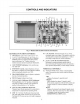
CONTROLS AND INDICATORS delayed sweep time base. This control has 23 steps, from 0.1 µS/div to 2 S/div, in a 1-2-5 sequence. PULL INVert: When pushed in, the polarity of the channel 2 signal is normal. When pulled out, the polarity of the channel 2 signal is reversed, thus inverting the waveform. 19. CH2 VOLTS/DIV Control. Vertical attenuator for channel 2. Provides step adjustment of vertical sensitivity.
CONTROLS AND INDICATORS NORM: Selects normal triggered sweep operation. A sweep is generated only when an adequate trigger signal is present. TV-V: Used for triggering from television vertical sync pulses. Also serves as lo-pass/dc (high frequency reject) trigger coupling. TV-H: Used for triggering from television horizontal sync pulses. Also serves as hi-pass (low frequency reject) trigger coupling. 33. TRIGger LEVEL/PULL (-) SLOPE Control. TRIGGERING CONTROLS 30. HOLDOFF/PULL CHOP Control.
OPERATING INSTRUCTIONS NOTE EQUIPMENT PROTECTION PRECAUTIONS All operating instructions in this chapter apply equally to all Models except for the sections on “Delayed Sweep Operation" and “Component Test”, which apply only to the Models 2125C & 2160C. Other differences are noted when necessary. The following precautions will help avoid damage to the oscilloscope. 1. Never allow a small spot of high brilliance to remain stationary on the screen for more than a few seconds.
OPERATING INSTRUCTIONS 2. Press the red POWER pushbutton (Model 2120C & 2160C), or rotate the POWER control clockwise “away from "OFF" (Model 2125C & 2160C). OPERATING TIPS The following recommendations will help obtain the best performance from the oscilloscope. 3. A trace should appear on the CRT. Adjust the trace brightness with the INTENSITY control, and the trace sharpness with the FOCUS control. 1.
OPERATING INSTRUCTIONS 3. To view both waveforms simultaneously, set the VERTical MODE switch to DUAL and select either ALT (alternate) or CHOP with the PULL CHOP switch. TRIGGERING These Oscilloscopes provide versatility in sync triggering for ability to obtain a stable, jitter-free display in single-trace, or dual-trace operation. The proper settings depend upon the type of waveforms being observed and the type of measurement desired.
OPERATING INSTRUCTIONS the control is centered, the threshold level is set at the approximate average of the signal used as the triggering source. Proper adjustment of this control usually synchronizes the display. Trigger SOURCE Switch The trigger SOURCE switch (CH 1, CH 2, etc.) selects the signal to be used as the sync trigger. 1. If the SOURCE switch is set to CH 1 (or CH 2) the channel 1 (or channel 2) signal becomes the trigger source regardless of the VERTICAL MODE selection.
OPERATING INSTRUCTIONS This control is usually set to the MIN position (fully counterclockwise) because no additional holdoff period is necessary. The HOLDOFF control is useful when a complex series of pulses appear periodically such as in Fig. 4B. Improper sync may produce a double image as in Fig. 4A. Such a display could be synchronized with the VAR SWEEP control, but this is impractical because time measurements are then uncalibrated.
OPERATING INSTRUCTIONS component test function can be used to view the signatures of resistors, capacitors, inductors, diodes, and other semiconductor devices. Devices may be analyzed in-circuit or out-of-circuit and combinations of two or more devices may be displayed simultaneously. Each component produces a different signature and the components can be analyzed as outlined below. Delayed Sweep 100 90 10 0 Component Test mode is activated by depressing the COMPonent TEST switch.
OPERATING INSTRUCTIONS Fig. 6. Typical Resistive Signatures.
OPERATING INSTRUCTIONS Inductors Like capacitance, a purely inductive impedance produces a signature that is an ellipse or circle and value is determined by the size and shape of the ellipse. A very high inductance causes the ellipse to flatten out horizontally and a very low inductance causes the ellipse to flatten out vertically. Values from about 0.05 H to about 5 H are within measurement range. Values below 0.
OPERATING INSTRUCTIONS Semiconductors Purely semiconductor devices (such as diodes and transistors) will produce signatures with straight lines and bends. Typical diode junctions produce a single bend with a horizontal and vertical line as shown in Fig. 9. Zener diodes produce a double bend with two vertical and one horizontal line as shown in Fig. 10 (value is determined by the distance of the leftmost vertical component from the center graduation on the CRT).
MAINTENANCE PERIODIC ADJUSTMENTS WARNING Probe compensation and trace rotation adjustments should be checked periodically and adjusted if required. These procedures are given below. The following instructions are for use by qualified service personnel only. To avoid electrical shock, do not perform any servicing other than contained in the operating instructions unless you are qualified to do so. Probe Compensation 1. Connect probes to CH 1 and CH 2 input jacks.
MAINTENANCE CALIBRATION CHECK INSTRUMENT REPAIR SERVICE A general check of calibration accuracy may be made by displaying the output of the CAL terminal on the screen. This terminal provides a square wave of 2 V p-p. This signal should produce a displayed waveform amplitude of four divisions at .5 V/div sensitivity for both channel 1 and 2 (with probes set for direct). With probes set for X10, there should be four divisions amplitude at 50 mV/div sensitivity.
APPENDIX IMPORTANT CONSIDERATIONS FOR RISE TIME AND FALL TIME MEASUREMENTS Error in Observed Measurement Calculated Measurements The observed rise time (or fall time) as seen on the CRT is actually the cascaded rise time of the pulse being measured and the oscilloscope’s own risetime.
23
NOTE: If input signal is not synchronized correctly on CRT display Frequency counter may have incorrect measurements. To check power line frequency with the 2121C set Trigger SOURCE switch to LINE position. There is no manual synchronization necessary in this mode, Counter will show Line frequency automatically. To activate the dedicated frequency counter input, separate from Oscilloscope cannels, set Time /Div switch to any range under red FREQ.≥100KHz label. Set SOURCE switch to EXT position.
INFORMATION One of the best tutorials on oscilloscopes in the industry. Valuable to those with little knowledge of oscilloscopes as well as the experienced technician or engineer who wishes to refresh their memory or explore new uses for oscilloscopes. Download your FREE copy from our Web site www.bkprecision.
22820 Savi Ranch Parkway, Yorba Linda, CA 92887 ©2013 B+K Precision Corp.