
Instruction Manual

3. To view both waveforms simultaneously, set the
VERTical MODE switch to DUAL and select either
ALT (alternate) or CHOP with the PULL CHOP
switch.
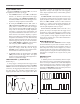
4. In the ALT sweep mode (PULL CHOP switch
pushed in), one sweep displays the channel 1 signal
and the next sweep displays the channel 2 signal in an
alternating sequence. Alternate sweep is normally
used for viewing high-frequency or high-speed wave-
forms at sweep times of 1 ms/div and faster, but may
be selected at any sweep time.
5. In the CHOP sweep mode (PULL CHOP switch
pulled out), the sweep is chopped (switched) between
channel 1 and channel 2. Using CHOP, one channel
does not have to “wait” for a complete swept display
of the other channel. Therefore, portions of both chan-
nel’s waveforms are displayed with the phase relation-
ship between the two waveforms unaltered. Chop
sweep is normally used for low-frequency or low-
speed waveforms at sweep times of 1 ms/div and
slower; or where the phase relationship between chan-
nel 1 and channel 2 requires measurement.
If chop sweep is used at sweep times of 0.2 ms/div and
faster, the chop rate becomes a significant portion of
the sweep and may become visible in the displayed
waveform. However, you may select chop sweep at
any sweep time for special applications.
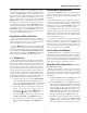
6. Adjust the channel 1 and 2
▲
▼
POSition controls to
place the channel 1 trace above the channel 2 trace.
7. Set the CH 1 and CH 2 VOLTS/DIV controls to a
position that gives 2 to 3 divisions of vertical deflec-
tion for each trace. If the display on the screen is
unsynchronized, refer to the “Triggering” paragraphs
in this section of the manual for procedures for setting
triggering and sweep time controls to obtain a stable
display showing the desired number of waveforms.
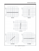
8. When the VERTical MODE switch is set to ADD, the
algebraic sum of CH 1 + CH 2 is displayed as a single
trace. When the PULL INV switch is pulled out, the
algebraic difference of CH 1 – CH 2 is displayed.
9. If two waveforms have no phase or frequency relation-
ship, there is seldom reason to observe both wave-
forms simultaneously. However, these oscilloscopes
do permit the simultaneous viewing of two such unre-
lated waveforms, using alternate triggering. Refer to
the paragraphs on “Triggering - Trigger SOURCE
Switch”, for details on alternate triggering.
TRIGGERING
These Oscilloscopes provide versatility in sync
triggering for ability to obtain a stable, jitter-free display
in single-trace, or dual-trace operation. The proper settings
depend upon the type of waveforms being observed and
the type of measurement desired. An explanation of the
various controls which affect synchronization is given to
help you select the proper setting over a wide range of
conditions.
Trigger COUPLING Switch
1. In the AUTO position, automatic sweep operation is
selected. In automatic sweep operation, the sweep
generator free-runs to generate a sweep without a
trigger signal. However, it automatically switches to
triggered sweep operation if an acceptable trigger
source signal is present. The AUTO position is handy
when first setting up the scope to observe a waveform;
it provides sweep for waveform observation until other
controls can be properly set. Once the controls are set,
operation is often switched back to the normal trigger-
ing mode, since it is more sensitive. Automatic sweep
must be used for dc measurements and signals of such
low amplitude that they will not trigger the sweep.
2. The NORM position provides normal triggered
sweep operation. The sweep remains at rest until the
selected trigger source signal crosses the threshold
level set by the TRIG LEVEL control. The trigger
causes one sweep to be generated, after which the
sweep again remains at rest until triggered. In the
normal triggering mode, there will be no trace unless
an adequate trigger signal is present. In the ALT
VERTICAL MODE of dual trace operation with the
SOURCE switch also set to ALT, there will be no
trace unless both channel 1 and channel 2 signals are
adequate for triggering. Typically, signals that pro-
duce even one division of vertical deflection are ade-
quate for normal triggered sweep operation.
3. The TV H and TV V positions are primarily for
viewing composite video waveforms. Horizontal sync
pulses are selected as trigger when the trigger COU-
PLING switch is set to the TV H position, and vertical
sync pulses are selected as trigger when the trigger
COUPLING switch is set to the TV V position. The
TV H and TV V positions may also be used as low
frequency reject and high frequency reject coupling,
respectively. Additional procedures for observing video
waveforms are given later in this section of the manual.
OPERATING INSTRUCTIONS
13