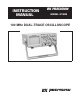
+ PRECISION BK INSTRUCTION MANUAL ® MODEL 2190B 100 MHz DUAL-TRACE OSCILLOSCOPE BK PRECISION + ®
TEST INSTRUMENT SAFETY WARNING Normal use of test equipment exposes you to a certain amount of danger from electrical shock because testing must often be performed where exposed high voltage is present. An electrical shock causing 10 milliamps of current to pass through the heart will stop most human heartbeats. Voltage as low as 35 volts dc or ac rms should be considered dangerous and hazardous since it can produce a lethal current under certain conditions.
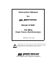
Instruction Manual for + BK PRECISION ® Model 2190B 100 MHz Dual-Trace Oscilloscope ©2000 B+K Precision Corp. This symbol on oscilloscope means “refer to instruction manual for further precautionary information”. This symbol appears in the manual where the corresponding information is given.
TABLE OF CONTENTS Page Page OPERATING INSTRUCTIONS (Continued) TEST INSTRUMENT SAFETY . . . . . . inside front cover X−Y Operation . . . . . . . . . . . . . . . . . . . . . . . . . . . . . 15 FEATURES . . . . . . . . . . . . . . . . . . . . . . . . . . . . . . . . . . . . 3 Video Signal Observation . . . . . . . . . . . . . . . . . . . . . 15 SPECIFICATIONS . . . . . . . . . . . . . . . . . . . . . . . . . . . . . . 5 Delayed Sweep Operation. . . . . . . . . . . . . . . . . . . . .
FEATURES LOW COST, HIGH PERFORMANCE VERTICAL FEATURES B+K Precision Model 2190B is one of the most economical 100 MHz analog oscilloscopes on the market, yet it has all of the high performance features needed for most applications, including delayed time base, bandwidth limiter, and Y axis output. This oscilloscope is built by and backed by B+K Precision, a company that has been selling reliable, durable, value priced test instruments for over 50 years.
FEATURES AUTO Sweep Selectable AUTO sweep provides sweep without trigger input, automatically reverts to triggered sweep operation when adequate trigger is applied. X−Y Operation Channel 1 can be applied as horizontal deflection (X-axis) while channel 2 provides vertical deflection (Y-axis). Five Trigger Sources Five trigger source selections, including CH 1, CH 2, alternate, EXT, and LINE. Built-in Probe Adjust Square Wave A 2 V p-p, 1 kHz square wave generator permits probe compensation adjustment.
SPECIFICATIONS CRT: HORIZONTAL AMPLIFIER Type: 6-inch rectangular with integral graticule, P31 phosphor. (Input through channel 1 input) Accelerating Voltage: 12 kV. X−Y mode: CH 1 = X axis. CH 2 = Y axis. Phosphor: P31. Sensitivity: Same as vertical channel 2. Trace Rotation: Electrical, front panel adjustable. Input Impedance: Same as vertical channel 2. VERTICAL AMPLIFIERS (CH 1 and CH 2) Frequency Response: DC to 2 MHz (−3 dB). Display Area: 8 x 10 div (1 div = 1 cm).
SPECIFICATIONS Output Impedance: Approximately 50 ohms. Trigger Coupling: AUTO: Sweep free-runs in absence of suitable trigger signal. NORM: TV-V: TV-H: Frequency Response: 20 Hz to 100 MHz, −3 dB. Intensity Modulation Sweep triggered only by adequate trigger signal. Input Signal: TTL level, intensity increasing with more positive levels, decreased intensity with more negative levels. Video vertical sync pulses are selected. Also usable for high frequency reject. Input Impedance: Approximately 50 kΩ.
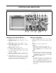
CONTROLS AND INDICATORS 15 28 14 1 2 3 4 5 29 27 25 26 24 23 22 21 30 10 11 13 12 7 6 8 9 16 17 18 19 20 Fig. 1. Model 2190A Controls and Indicators. GENERAL FUNCTION CONTROLS VERTICAL CONTROLS 1. ON Indicator. Lights when oscilloscope is “on”. 9. VERTical MODE Switch. Selects vertical display mode. Four-position lever switch with the following positions: 2. POWER Pushbutton. Turns oscilloscope “on” and “off”. CH1: Displays the channel 1 signal by itself.
CONTROLS AND INDICATORS 15. CH2 10. CH1 AC-GND-DC Switch. Three-position lever switch with the following positions: POSition/PULL INVert Control: POSition: Rotation adjusts vertical position of channel 2 trace. In X-Y operation, rotation adjusts vertical position of X-Y display. PULL INVert: When pushed in, the polarity of the channel 2 signal is normal. When pulled out, the polarity of the channel 2 signal is reversed, thus inverting the waveform. 16. CH2 VOLTS/DIV Control.
CONTROLS AND INDICATORS HORIZONTAL CONTROLS TRIGGERING CONTROLS 20. Main Time Base TIME/DIV Control. Provides step selection of sweep rate for the main time base. When the VARiable Sweep control is set to CAL, sweep rate is calibrated. This control has 23 steps, from 20 nS/div to 0.5 S/div, in a 1-2-5 sequence. 26. HOLDOFF/PULL NORM TRIG Control. HOLDOFF: Rotation adjusts holdoff time (trigger inhibit period beyond sweep duration).
CONTROLS AND INDICATORS 30. EXTernal TRIGger Jack. External trigger input for single- and dual-trace operation. TV-H: Used for triggering from television horizontal sync pulses. Also serves as hi-pass (low frequency reject) trigger coupling. LINE: Signal derived from input line voltage (50/60 Hz) becomes trigger. 29. TRIGger LEVEL/PULL (–) SLOPE Control. REAR PANEL CONTROLS (not shown) 31. Fuse Holder/Line Voltage Selector. Contains fuse and selects line voltage. 32. Power Cord Receptacle. 33.
OPERATING INSTRUCTIONS SAFETY PRECAUTIONS EQUIPMENT PROTECTION PRECAUTIONS WARNING The following precautions must be observed to help prevent electric shock. The following precautions will help avoid damage to the oscilloscope. 1. When the oscilloscope is used to make measurements in equipment that contains high voltage, there is always a certain amount of danger from electrical shock.
OPERATING INSTRUCTIONS OPERATING TIPS 2. Press the red POWER pushbutton. The following recommendations will help obtain the best performance from the oscilloscope. 3. A trace should appear on the CRT. Adjust the trace brightness with the INTENSITY control, and the trace sharpness with the FOCUS control. 1. Always use the probe ground clips for best results, attached to a circuit ground point near the point of measurement.
OPERATING INSTRUCTIONS 3. To view both waveforms simultaneously, set the VERTical MODE switch to DUAL and select either ALT (alternate) or CHOP with the PULL CHOP switch. TRIGGERING The Model 2190B Oscilloscope provides versatility in sync triggering for ability to obtain a stable, jitter-free display in single-trace, or dual-trace operation. The proper settings depend upon the type of waveforms being observed and the type of measurement desired.
OPERATING INSTRUCTIONS triggering threshold shifts to a more negative value. When the control is centered, the threshold level is set at the approximate average of the signal used as the triggering source. Proper adjustment of this control usually synchronizes the display. Trigger SOURCE Switch The trigger SOURCE switch (CH 1, CH 2, etc.) selects the signal to be used as the sync trigger. 1.
OPERATING INSTRUCTIONS permitted. The HOLDOFF control allows this period to be extended by a variable amount if desired. 3. Adjust the amount of vertical (Y axis) deflection with the CH 2 VOLTS/DIV and VARIABLE controls. This control is usually set to the MIN position (fully counterclockwise) because no additional holdoff period is necessary. The HOLDOFF control is useful when a complex series of pulses appear periodically such as in Fig. 4B. Improper sync may produce a double image as in Fig. 4A.
OPERATING INSTRUCTIONS 3. Shift the percentage of the display that is occupied by the main sweep by adjusting the DELAY TIME POSition control. Counterclockwise rotation causes more of the display to be occupied by the main sweep and clockwise rotation causes more of the display to be occupied by the delayed sweep. Delayed Sweep 100 90 4. Set the Sweep Mode switch to the DELAY position to display only the magnified delayed sweep portion of the display.
MAINTENANCE PERIODIC ADJUSTMENTS WARNING Probe compensation and trace rotation adjustments should be checked periodically and adjusted if required. These procedures are given below. The following instructions are for use by qualified service personnel only. To avoid electrical shock, do not perform any servicing other than contained in the operating instructions unless you are qualified to do so. Probe Compensation 1. Connect probes to CH 1 and CH 2 input jacks.
MAINTENANCE CALIBRATION CHECK INSTRUMENT REPAIR SERVICE A general check of calibration accuracy may be made by displaying the output of the CAL terminal on the screen. This terminal provides a square wave of 2 V p-p. This signal should produce a displayed waveform amplitude of four divisions at .5 V/div sensitivity for both channel 1 and 2 (with probes set for direct). With probes set for X10, there should be four divisions amplitude at 50 mV/div sensitivity.
APPENDIX IMPORTANT CONSIDERATIONS FOR RISE TIME AND FALL TIME MEASUREMENTS Error in Observed Measurement Calculated Measurements The observed rise time (or fall time) as seen on the CRT is actually the cascaded rise time of the pulse being measured and the oscilloscope’s own risetime.
LIMITED WARRANTY B+K Precision Corp. warrants to the original purchaser that its product, and the component parts thereof, will be free from defects in workmanship and materials for a period of three years from the date of purchase. B+K Precision Corp.
INFORMATION One of the best tutorials on oscilloscopes in the industry. Valuable to those with little knowledge of oscilloscopes as well as the experienced technician or engineer who wishes to refresh their memory or explore new uses for oscilloscopes. Download your FREE copy from our Web site www.bkprecision.
® + 1031 Segovia Circle, Placentia, CA 92870 © 2000 B+K Precision Corp.