
Manual

21
Probe Compensation
As an alternative method to Probe Check, you can manually perform this
adjustment to match your probe to the input channel.
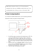
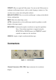
Figure 9 - Probe Compensation Setup
1. Set the Probe option attenuation in the channel menu to 10X. Do
so by pressing CH1 button and selecting “Probe” from menu.
Select 10X. Set the switch to 10X on the probe and connect the
probe to channel 1 on the oscilloscope. If you use the probe hook-
tip, ensure a proper connection by firmly inserting the tip onto the
probe.
2. Attach the probe tip to the PROBE COMP 3V connector and the
reference lead to the PROBE COMP Ground connector. Display
the channel and then push the “AUTO” button.
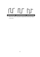
3. Check the shape of the displayed waveform.
Note. When the attenuation switch is set to 1X, the probe limits the
bandwidth of the oscilloscope to 10 MHz (according to Probe spec). To use
the full bandwidth of the oscilloscope, be sure to set the switch to 10X.