
Owner manual


27
* When the reference level is set below “Minimum”, “*S/W AMP” is displayed in Amplitude axis setting
values display area on the screen.
Calculation formula (conversion from dBm)
● A[dBμV] = 107 + X [dBm] ● B[dBmV] = 47 + X [dBm] ● C[dBV] = -13 + X [dBm]
● D[dBμV/m] = 68.8 / λ×√(X/Gar) [dBm] λ : Wavelength[m] Gar : Antenna absolute gain[times]
● E[dBμA/m] = 107 + X + F[dBm] F : Probe calibration coefficient[dB] **changes depending on the
frequency.
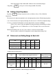
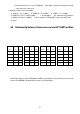
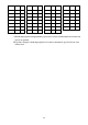
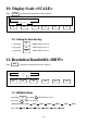
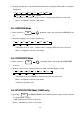
9.8 Relationship Between Reference Level and ATT/AMP (at dBm)
Internal input attenuator (ATT) and IF amplifier (AMP) are automatically set to the optimum values based on the
reference level (REFER). (The input attenuator cannot be set independently.)
REFER
(dBm)
ATT
(dB)
AMP
(dB)
REFER
(dBm)
ATT
(dB)
AMP
(dB)
REFER
(dBm)
ATT
(dB)
AMP
(dB)
REFER
(dBm)
ATT
(dB)
AMP
(dB)
10 25 0
-3 12 0
-16 20 21
-29 7 21
9 24 0
-4 11 0
-17 19 21
-30 6 21
8 23 0
-5 10 0
-18 18 21
-31 5 21
7 22 0
-6 9 0
-19 17 21
-32 4 21
6 21 0
-7 8 0
-20 16 21
-33 3 21