Instruction Manual Model 307A Analog Insulation & Continuity Meter
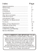
Index Safety Precautions........................................ Safety Notes................................................. Features ...................................................... Connections ................................................ Specifications ...... ....................................... Why Test is necessary ................................. Instrument Layout ........................................ Lid Instruction Label ....................................
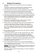
1. 1.1 1.2 1.3 1.4 1.5 1.6 1.7 1.8 Safety Precautions Electricity can cause severe injuries even with low voltages or currents. Therefore it is extremely important that you read the following information before using your Analog Insulation Tester. This Instrument must only be used and operated by a competent trained person and in strict accordance with the instructions. We will not accept liability for any damage or injury caused by misuse or non compliance with instructions and safety procedures.
2. Safety Notes Rated environmental conditions (1). Indoor use. (2). Installation Category . (3). Pollution Degree 2. (4). Altitude up to 2000M Meter is protected throughout by double insulation or reinforced insulation. Warning ! Risk of electric shock. Caution ! Refer to this manual before using the meter. 3. Features Ÿ High Quality Taut Band movement.
Ÿ Auto null of the test leads on continuity tests. Ÿ Very Low Battery Consumption. Ÿ On-Load battery check (+/-205mA load for worst case) operates on 8 dry batteries (AA, R6P type..) Ÿ Mirror scale. Ÿ Push and Turn locking switch for long and hand free testing. Ÿ Designed to meet international standards. Ÿ Supplied with High Quality test leads. 4. Connections ! LINE CAT.
5. Specifications INSULATION Test Voltage 250Vdc 500Vdc 1000Vdc +10%-0% +10%-0% +10%-0% Mirror scale 100MW 200MW 400MW Mid Scale 1MW 2MW 4MW Scale Multiplier x1/2 x1 x2 Accuracy ±3% Output Short-Circuit Current 1.3mA Regulated Output Voltage (up to 1mA current) 263.5V / 525V / 1052V CONTINUITY Low W 0 - 3W 0 - 500 W Test Leads / Fuse Zero W Adjustment by knob Output Short-Circuit Current 205mA Accuracy ±1.
6. Why test is necessary ? INSULATION Every electrical apparatus and installation need to be safe for the user and for the equipment itself. Electrical conductors of electricity need to be insulated from each other, so that they do not create electrical hazard or unnecessary consumption. Badly insulated circuits can create leakage current which can be dangerous and trip your GFCI, RCCB or ELCB.. Each country regulate those levels at which the insulation is acceptable.
7. Instrument Layout 4 3 5 N-E P-E ! FOR Vac: DO NOT PRESS PRESS TO TEST INSULATION MW 1000V/400MW ! 500V/200MW 250V/100MW 3W 500W LOCK 1 Batt. Check W CONTINUITY FOR CONTINUOUS TESTING, PRESS AND TURN ALWAYS ENSURE CIRCUIT TO TEST IS FREE OF VOLTAGE BEFORE PROCEEDING WITH CONTINUITY OR INSULATION TESTING. CATIII 600V 0W ZERO OHM ADJUST INSULATION-CONTINUITY METER 1. Test Button Switch. 2. Function Selector 3. Battery OK indicator 4. Mirror Scale 5. Live Circuit Warning Light 6.
INSTRUCTIONS ANALOG INSULATION-CONTINUITY TESTER -7- CONTINUITY TESTS - W Ranges 1. Select the desired ohm range, 3W or 500W. 2. Short the test leads, press test button and adjust the ohms zero ADJ to zero the pointer on the 0W (green scale) 3. Check the circuit is not LIVE. 4. Connect the test leads to the circuit under test. Press the test button. Read the selected range directly. GENERAL: Ÿ For AC Voltmeter, do not press test button, this is the default mode of the instrument.
9.Preparation for Measurement Before testing Always check the following. At Power "ON", check that Bat. OK led lit. And check that there is no visual damage to the Instrument or test leads. Check the test Leads continuity 1. Connect the leads to the Instrument. 2. Zero the test leads while on the 3 ohm range.. 3. This will indicate your that continuity of the test leads is ok. 4. Verify that the test leads insulation is in good condition. 10. Functions 10.
10.2 DC Warning The DC warning buzzer will beep continuously when DC voltage is higher than 30Vdc on the test probes and the test button is Not pressed. The neon light "circuit live" will lit when the voltage on the test probes is higher than 90Vdc and the test button is not pressed. 10.3 AC Warning The AC warning buzzer will beep continuously when AC voltage is higher than 20Vac on the test probes and the test button is Not pressed.
10.5 Low ohms measurement 0 - 500W FOR Vac: DO NOT PRESS PRESS TO TEST ! INSULATION MW 1000V/400MW 500V/200MW 250V/100MW 3W N-E LOCK ! 500W P-E Batt. Check W CONTINUITY FOR CONTINUOUS TESTING, PRESS AND TURN Always check for voltage before testing and measuring on a circuit. This instrument is intended for measuring Low W and Insulation resistance on un-energized circuits only. Use the procedure explained at points 7.2, 7.3, 7.4.
10.6 Low ohms measurement 0 - 3W FOR Vac: DO NOT PRESS PRESS TO TEST ! INSULATION MW 1000V/400MW 500V/200MW 250V/100MW 3W N-E LOCK ! FOR CONTINUOUS TESTING, PRESS AND TURN 500W P-E Batt. Check W CONTINUITY Always check for voltage before testing and measuring on a circuit. This instrument is intended for measuring Low W and Insulation resistance on un-energized circuits only. Use the procedure explained at points 7.2, 7.3, 7.4.
10.7 Insulation Resistance Measurement @ 250Vdc FOR Vac: DO NOT PRESS PRESS TO TEST ! INSULATION MW 1000V/400MW 500V/200MW 250V/100MW 3W N-E LOCK ! 500W P-E Batt. Check W CONTINUITY FOR CONTINUOUS TESTING, PRESS AND TURN Always check for voltage before testing and measuring on a circuit. This instrument is intended for measuring Low W and Insulation resistance on un-energized circuits only. Use the procedure explained at points 7.2, 7.3, 7.4.
10.8 Insulation Resistance Measurement @ 500Vdc FOR Vac: DO NOT PRESS PRESS TO TEST ! INSULATION MW 1000V/400MW 500V/200MW 250V/100MW 3W N-E LOCK ! 500W P-E Batt. Check W CONTINUITY FOR CONTINUOUS TESTING, PRESS AND TURN Always check for voltage before testing and measuring on a circuit. This instrument is intended for measuring Low W and Insulation resistance on un-energized circuits only. Use the procedure explained at points 7.2, 7.3, 7.4.
10.9 Insulation Resistance Measurement @ 1000Vdc FOR Vac: DO NOT PRESS PRESS TO TEST ! INSULATION MW 1000V/400MW 500V/200MW 250V/100MW 3W N-E LOCK ! 500W P-E Batt. Check W CONTINUITY FOR CONTINUOUS TESTING, PRESS AND TURN Always check for voltage before testing and measuring on a circuit. This instrument is intended for measuring Low W and Insulation resistance on un-energized circuits only. Use the procedure explained at points 7.2, 7.3, 7.4.
11. Battery & Fuse Replacement 11.1 Battery Replacement Your Analog insulation tester's battery is situated under the tester. The Bat. OK will not lit when battery need to be replaced. Disconnect the test leads from the Instrument, remove the battery cover and the batteries. Replace with eight 1.5V R6 or L6 batteries, taking care to observe the correct polarity. Replace battery and the battery cover. 11.2 Fuse replacement The Fuse is located next to the Batteries.
12. Calibration & Servicing Contact your nearest distributor about Calibration Certificate and Servicing . Before returning the Instrument, ensure that : Ÿ the leads have been checked for continuity and signs of damage. Ÿ The batteries are in good condition. 13. Cleaning & Storage Periodically wipe the case with a damp cloth and detergent; do not use abrasives or solvents. If the meter is not to be used for long periods or longer than 60 days, remove the batteries and store them separately.
14. Limited One-year Warranty B&K Precision warrants to the original purchaser that its products and the component parts thereof, will be free from defects in workmanship and materials for a period of one year from date of purchase from an authorized B&K Precision distributor. B&K Precision will, without charge, repair or replace, at its option, defective product or component parts. Returned product must be accompanied by proof of the purchase date in the form of a sales receipt.
15. Service Information Warranty Service: Please return the product in the original packaging with proof of purchase to the address below. Clearly state in writing the performance problem and return any leads, probes, connectors and accessories that you are using with the device. Non-Warranty Service: Return the product in the original packaging to the address below. Clearly state in writing the performance problem and return any leads, probes, connectors and accessories that you are using with the device.
B&K Precision 22820 Savi Ranch Parkway Yorba Linda, CA 92887 U.S.A. www.bkprecision.com Printed in Taiwan / Ver. 1.