Instruction Manual Model 308A Digital Insulation & Continuity Meter
INDEX PAGE INSTRUMENT LAYOUT............................... 1 INTRODUCTION........................................ 2 SAFETY NOTES......................................... 3 FEATURES................................................ 4 MEASURING METHODS............................. 5-7 SPECIFICATIONS...................................... 8-9 MAINTENANCE.......................................... 10 LIMITED ONE-YEAR WARRANTY................ 11 SERVICE INFORMATION............................
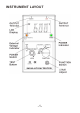
INSTRUMENT LAYOUT -1-
INTRODUCTION NOTE This meter has been designed and tested according to IEC publication 348 , safety requirements for electronic measuring apparatus , IEC-1010 (EN 61010) and other safety standards . Follow all warnings to ensure safe operation . WARNING READ "SAFETY NOTES" ( NEXT PAGE ) BEFORE USING THE METER .
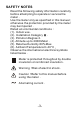
SAFETY NOTES — Read the following safety information carefully before attempting to operate or service the meter . — Use the meter only as specified in this manual ; otherwise the protection provided by the meter may be impaired . — Rated environmental conditions : (1). Indoor use . (2). Installation Category . (3). Pollution Degree 2 . (4). Altitude up to 2000 Meter . (5). Relative Humidity 80% Max. (6). Ambient Temperature 0~40 °C — Observe the international electrical symbols listed below .
FEATURES — 3 1/2 Digit Insulation Tester . — 68mm(2.677")x34mm(1.33") large LCD display . — Three Insulation test voltage 250V,500V,1000V . — External voltage warning indication — Automatic circuit discharge . — Test Insulation at rated voltage into a 1 mA load . — 200 mA continuity short circuit test current . — AC voltage measurement . — Fuse protection . — Meet IEC 1010 CAT. , BS 16 th edition .
MEASURING METHODS Operation caution Observe all safety precautions when the FUNCTION switch is set to either the 200M (250,500V) or the 2000M (1000V) position . Connect the meter test leads to the circuit under test before operating the TEST switch . Do not touch the clip ends of the test leads when the TEST switch is pressed . Some electrical equipment , especially cables , may retain an electrical charge when disconnected from the line .
— Always check the following before testing : The "Battery Low" indicator is not showing. There is no visual damage to the instrument or test leads. — Test Lead Continuity: Select the CONTINUITY function and 20W range. Short the test leads together. An over-range ( "1" ) indication will mean that the leads are faulty or instrument fuse is blown. (See "Fuse Replacement" section) — Insulation Resistance Testing: Warning: Insulation tests should be conducted on circuits that are de-energised .
Caution: Never turn the function dial whilst the button is depressed. This may damage the instrument. Never touch the circuit under test during insulation testing. When testing is complete ensure that the test buttonis released before the test leads are disconnected . This is because the system may be charged up and it must be allowed to discharge through the tester's Internal discharge resistor . — Continuity testing (Resistance tests) : Warning: Ensure circuit are not live before commencing testing .
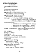
SPECIFICATIONS test leads. — Test Lead Continuity: S — Insulation resistance Measuring range : 0-200M (250V,500V DC ±10%) Resolution : 1 count / 100K 0-2000M (1000V DC ±10%) Resolution : 1 count / 1M Accuracy : ±1.5% rdg. ±5dgt. (200M range ±3%rdg. ±3dgt. (under 1G / 2000M ±5%rdg. ±5dgt. (under 2G 2000M Output current : 1 mA DC min. at 0.25 M (250V range) 1 mA DC min. at 0.5 M (500V range) 1 mA DC min. at 1 M (1000V range) Power consumption : Max. consumption current approx. 250mA .
— — — — Open circuit terminal voltage : 4 V DC min. Short circuit terminal current : 210 mA DC min. Power consumption: Max. consumption current approximately 160mA Buzzer sound below : under 10 (on 20 range) Withstand :Meet IEC-1010 safety requirements Category . Dimension :170 165 92 mm 6.7 6.5 3.6 inch with housing front cover Weight : 1.04 kg ( battery included ) Standard Accessories : Batteries 1.5V , size AA (R6) 8 pieces Test Leads 1 pair Fuse 0.5A , 250V 1 piece Instruction Manual 1 vol.
MAINTENANCE Caution: Always disconnect the test leads from the instrument before attempting battery or replacement . — Batteries replacement : Please replace batteries when the "Battery Low" indicator was shown on the LCD. Disconnect the test leads from the instrument, remove the battery compartment lid and the batteries. Replace with eight 1.5V AA (R6) batteries, taking care to observe correct polarity. Alkaline batteries are recommended. Replace the battery compartment lid.
Limited One-year Warranty B&K Precision warrants to the original purchaser that its products and the component parts thereof, will be free from defects in workmanship and materials for a period of one year from date of purchase from an authorized B&K Precision distributor. B&K Precision will, without charge, repair or replace, at its option, defective product or component parts. Returned product must be accompanied by proof of the purchase date in the form of a sales receipt.
Service Information Warranty Service: Please return the product in the original packaging with proof of purchase to the address below. Clearly state in writing the performance problem and return any leads, probes, connectors and accessories that you are using with the device. Non-Warranty Service: Return the product in the original packaging to the address below. Clearly state in writing the performance problem and return any leads, probes, connectors and accessories that you are using with the device.
B&K Precision 22820 Savi Ranch Parkway Yorba Linda, CA 92887 U.S.A. www.bkprecision.com Printed in Taiwan / Ver. 1.