Instruction Manual Model 310 Digital Milli-Ohm Meter
DESCRIPTION SAFETY RULES.................................................... PAGE 01 GENERAL DESCRIPTION.................................... 02-03 FRONT PANEL LAYOUT....................................... 04 PREPARATION FOR USE.................................... 05 PRELIMINARY CHECKS...................................... 05 PRECAUTIONS..................................................... 06 MEASURING......................................................... 07 SIMPLIFIED MEASUREMENT.............
SAFETY RULES The meter has been designed with safety in mind. However, no design can completely protect against incorrect use. Electrical circuits are dangerous and lethal through lack of caution or poor safety practice. The following rules should reduce the danger • Read the User's manual carefully and completely before using the instrument. Fully understand the instructions before using this product. Follow the instructions for every test. Take all the necessary precautions.
GENERAL DESCRIPTION The meter digital milli-ohmmeter is a battery operated instrument wich supply a low current to the circuit under test, with which, stable, accurate measurement of low resistance can be made, still, over a wide range of values. Resolution on the lowest range is 100µ ohm and on the highest range, 1 ohm. The meter has 5 measuring ranges, from 200.0milli-ohm to 2000 ohms. Measurements are displayed on a 3½ digit custom liquid crystal display with large digits.
The meter has a built-in custom 3½ digit liquid crystal display can be viewed in most lightning conditions. This display indicates the diferentes conditions (Hold, m, buzzer, polarity condition of load, + or -, automatic decimal point change). The ranges are selected by a 5 position rotary switch, and a test is initiated by pressing the ON push-button. The instrument takes measurements for 10 seconds if the "ON" "TEST re" presentative" button is depressed for less than 2 seconds.
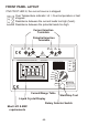
FRONT PANEL LAYOUT If NO TEST LED lit, the current source is stopped. NO TEST RP RC Over Temperature indicator. Lit = Over-temperature or test stopped. Resistance between the current leads too high (fuse!). Resistance between the potential leads too high. Current Injection Terminals Potential Injection Terminals C1 P1 P2 C2 MAX. DC20V MICROPROCESSOR CONTROLLED HOLD AC DC MAX MIN AUTO-HOLD Test Current Range 2000 W 1mA 200.0 W 10mA 20.00 W 10mA 2000m W 100mA 100mA 200.
PREPARATION FOR USE When unpacked, the tester should be inspected for any visible signs of damage, and the preliminary checks described in the user's manual should be performed to ensure that it is operating correctly. If there is any sign of damage, or if the instrument does not operate correctly, return it to your nearest supplier. PRELIMINARY CHECKS Check the battery • If the battery symbol is shown on the LCD, then replace the batteries with new alkalines batteries before proceeding.
PRECAUTIONS • Always ensure that the circuit to be measured is switched "OFF", isolated and completely de-energised before connecting the test Leads. • If it is probable that the instrument's protection has been impaired due to electrical, mechanical or environmental damage, it must not be used. It should be returned to your nearest distributor or agent for checking and repair. • To prevent damage to the liquid crystal display, the minimum storage temperature of -20°C must be observed.
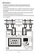
MEASURING • Perform the preliminary checks before proceeding with measurement and ensure that the precautions listed are observed. • Connect the test leads (color coded) to the instrument as shown. • The current test leads must always be outside of the potential test leads. • Please note that the shorter the potential test leads, the better long potential test leads will pick up noise. • Screened test leads are recommended for better environmental noise rejection.
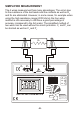
SIMPLIFIED MEASUREMENT The 4 wires measurement has many advantages. The errors due to the resistance of the test leads and the contacts as well as RA and RB are eliminated. However, in some cases, for example when using the high resistance range (2000 ohms) the four wires method is not necessary to still have a good percentage of accuracy (compared to the full scale). The simplified method of two wires can be used without too much problems. C1 and P1 can be shorted as well as C2 and P2.
APPLICATIONS The meter Digital milli-ohmmeter, with its measuring range of 100 µohms to 2000 ohms, is suitable for a wide range of applications such as • Measuring the winding resistance of electric motors, generators And transformers. • Bond testing in mines, aircraft, railways, ships, domestic and industrial wiring installations. • Measuring the ring main continuity testing in industrial and domestic wiring installations.
TEST LEADS The test leads supplied with the instrument are suitable for connecting to conductors up to 17mm in diameter or bus bars 17mm tick. There will be,instances where the item being measured require larger jaws, and the user is advised to make up his own leads. There will be occasions when longer leads are required due to the geometry of the item being tested. Some guidance notes should assit in the assembly of such leads: Length of the potential leads should be as short as possible. Insulated 16/0.
THERMAL EFFECTS Temperature can have a significant effect on the performance of a digital milli-ohmmeter due to the temperature coefficient of the resistance under test and thermal EMF's across the dissimilar conductors. Most conductors have a large temperature coefficient of resistance. For example 0.4%/°C for copper. A copper conductor that has a resistance of 10.00m ohm at 20°C will increase to 10.40m ohm at 30°C. This change should be taken into account when making measurements.
FUSES REPLACEMENT There are three fuses l Power Supply Fuse The power supply fuse is situated under the tester. Open the battery compartment, and replace the fuse with the same type (1.5A, >24V, Slow Blow) l Current Circuit Fuse Fuse protection is provided on the current terminals. This fuse is situated under the Printed Circuit Board. To access it, you need to unscrew the four mounting screws which are holding the font panel.
INPUT LIMITS & PROTECTIONS The maximum continuous voltage which can be applied across the potential and current leads is around 10.7V. Applying more than that voltage will automatically blow their respective fuses. However, the crowbar trigger can be factory adjusted for your application. We have specially selected that method to stop damaging the instrument, should it be misused.
SPECIFICATIONS ELECTRICAL Measuring Ranges 0-200.0m ohms in steps of 100µ ohm 0-2000m ohms in steps of 1m ohm 0-20.00 ohms in steps of 10m ohm 0-200.0 ohms in steps of 100m ohm 0-2000 ohms in steps of 1 ohm Accuracy ±0.5% of reading ±2 digits over the Operating temperature range, -15°C to +55°C, with the supplied test leads. Test Current 1mA => 2000 ohms range. 10mA => 200 / 20 ohms ranges. 100mA => 2000m / 200m ohm ranges. Test Current Accuracy ±0.3% Protection Fuses Supply = 1.
SPARES & ACCESSORIES At the date of printing this user's manual, accessories were not yet available. Please contact the factory for further information. Spares are available from your nearest distributor. LIMITED ONE-YEAR WARRANTY B&K Precision warrants to the original purchaser that its products and the component parts thereof, will be free from defects in workmanship and materials for a period of one year from date of purchase from an authorized B&K Precision distributor.
CLEANING & STORAGE Periodically wipe the case with a damp cloth and detergent do not use abrasives or solvents. If the meter is not to be used for periods of longer than 60 days, remove the batteries and store them separately. BATTERY & FUSE REPLACEMENT l Battery Replacement • The tester continuously monitors the battery voltage and indicates when the batteries need to be replaced. • The tester's battery is situated under the tester.
CAT IV - Is for measurements performed at the source of the lowvoltage installation. CAT III - Is for measurements performed in the building Installation CAT II - Is for measurements performed on circuits directly connected to the low-voltage installation. CAT I - Is for measurements performed on circuits not directly Connected to mains. Due to our policy of constant improvement and development, we reserve the right to change specifications without notice.
B&K Precision 22820 Savi Ranch Parkway Yorba Linda, CA 92887 U.S.A. www.bkprecision.com Printed in Taiwan / Ver. 1.