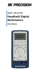
Model: 392 and 393 Handheld Digital Multimeters USER MANUAL
Safety Summary The following safety precautions apply to both operating and maintenance personnel and must be observed during all phases of operation, service, and repair of this instrument. Before applying power, follow the installation instructions and become familiar with the operating instructions for this instrument. If this device is damaged or something is missing, contact the place of purchase immediately.
WARNINGS AND CAUTIONS WARNING and CAUTION statements, such as the following examples, denote a hazard and appear throughout this manual. Follow all instructions contained in these statements. A WARNING statement calls attention to an operating procedure, practice, or condition, which, if not followed correctly, could result in injury or death to personnel.
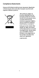
Compliance Statements Disposal of Old Electrical & Electronic Equipment (Applicable in the European Union and other European countries with separate collection systems) This product is subject to Directive 2002/96/EC of the European Parliament and the Council of the European Union on waste electrical and electronic equipment (WEEE) , and in jurisdictions adopting that Directive, is marked as being put on the market after August 13, 2005, and should not be disposed of as unsorted municipal waste.
CE Declaration of Conformity The power supply meets the requirements of 2006/95/EC Low Voltage Directive and 2004/108/EC Electromagnetic Compatibility Directive with the following standards.
Safety Symbols Electrical Shock hazard. Caution, refer to the operating user manual for warning information to avoid hazard or personal injury and prevent damage to instrument. CATI CATII CATIII CATIV Category I overvoltage conditions. Measurement instruments whose measurement inputs are not intended to be connected to the mains supply. The voltages in the environment are typically derived from a limited-energy transformer or a battery. Category II overvoltage conditions.
Table of Contents Safety Summary .......................................................................... 3 1 General Information ............................................................. 9 1.1 Product Overview ......................................................... 9 1.2 Package Contents ......................................................... 9 1.3 Front Panel Overview ................................................. 10 Front Panel Description .............................................
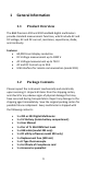
1 General Information 1.1 Product Overview The B&K Precision 392 and 393 handheld digital multimeters provide standard measurement functions, which include AC and DC voltage, AC and DC current, resistance, capacitance, diode, and continuity. Features: • 60,000 Count display resolution • DC Voltage measurement up to 1000 V • AC Voltage measurement up to 750 V • AC and DC Current up to 20 A • USB interface for remote communication (model 393) 1.
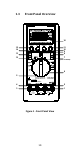
1.3 Front Panel Overview % 0 15 14 13 10 RANGE cal>2s 20 30 40 MIN/MAX REL ± 12 + + mV Ω ns 50 16 60 HOLD SHIFT Digital Multimeter 7 Hz % V (6000 or RS232) µ mV 11 10 9 8 + V + C F 6 5 30V MAX 4 20A K-Type AUTO POWER OFF TRUE RMS AC+DC CATIII 1000V CATIV 600V + MAX 400mA µ A mA COM VΩ CAT.
Front Panel Description 1 VΩHz%ns 2 COM 3 20A 4 μAmA 5 K-Type 6 Function/Range Rotary Switch 7 6000/RS232 8 Shift 9 Backlight 10 MAX/MIN 11 HOLD 12 HFR The positive input terminal for Voltage, Ohms, Frequency, Duty Cycle, Conductance, Diode measurements. Connection is made using the red test lead. The negative (ground) input terminal for all measurement modes. Connection is made to it using the black test lead. The positive input terminal for up to 20 A current measurement.
13 PEAK+ Cal>2S 14 REL Δ 15 RANGE 16 Display Records the peak+ and peak- values of a measurement with a response time as low as 1ms. Pressing the button for more than 2 seconds will exit the mode. Pressing the REL button enters the Relative mode where the meter will use the displayed value at the time of the button press an offset value and that value will be subtracted from the display of future measurements.
2 Getting Started 2.1 Using the Digital Multimeter With no signal present, set the rotary switch to the desired measurement function. Ensure proper insertion of the test leads so they correspond with the type of measurement you wish to perform, see the following instructions to understand the proper lead configuration for each measurement type. 2.2 DC and AC Voltage Measurements Turn the rotary switch to the corresponding symbol for the measurement you would like to perform.
2.3 DC and AC Current Measurements Turn the rotary switch to the corresponding symbol for the measurement you would like to perform. Current measurements can be made in low current or high current mode. In low current measurement mode, you can measure up to 400 mA. Connect to the low current mA terminal and select one of the two ranges. In high current measurement mode, you can measure up to 20 A by selecting one of the two ranges and connecting to the 20 A input terminal.
WARNING: Do not connect more than 400 mA DC current across the mA input terminal or the protection fuse will be tripped. Higher Current Measurements (Up to 20 A) Follow these steps to make measurements up to 20 A. 1. Connect the negative (-) side with the black test lead to the COM input. 2. Connect the positive (+) side with the red test lead to the 20 A input. 3. Probe with the test leads to the DUT and take the measured reading on display. 4.
2.4 Make Resistance Measurements Turn the rotary switch to the corresponding symbol for the measurement you would like to perform. CAUTION: Always connect the test leads to the instrument inputs first before connecting the DUT to avoid potential shock hazard. Follow these steps to make a measurement. 1. Connect the black test lead to the COM input. Note that the measurement voltage polarity is positive on COM input. 2. Connect the red test lead to the VΩHz%ns input. 3.
2.5 Make Diode Measurements Turn the rotary switch to the corresponding symbol for the measurement you would like to perform. Press the shift button to cycle to the diode function. CAUTION: Always connect the test leads to the instrument inputs first before connecting the DUT to avoid potential shock hazard. Follow these steps to make a measurement. 1. Connect the black test lead to the COM input. 2. Connect the red test lead to the VΩHz%ns input. 3.
Follow these steps for continuity testing: 1. Connect the black test lead to the COM input. 2. Connect the red test lead to the VΩHz%ns input. 3. Connect the two leads together to verify that the continuity function is working properly. The instrument should have a continuous beep sound. 4. Probe with the test leads to the DUT and take the measured reading on display. 5. If continuity is good, it will have a continuous beep sound. 20 A uAmA COM V.
CAUTION: Always connect the test leads to the instrument inputs first before connecting the DUT to avoid potential shock hazard. Follow these steps to make a capacitance measurement. 1. Connect the black test lead to the COM input. This will connect to the negative side of your capacitor. 2. 3. 4. Connect the red test lead to the uAmA input. This will connect to the positive side of your capacitor. Probe with the test leads to the DUT and take the measured reading on display.
Follow these steps to make a temperature measurement. 1. Plug the K-type thermocouple directly into the meter. 2. Apply the thermocouple bead tip to the sample you would like to measure the temperature of. 3. Take measured reading from the display. 2.9 Make Frequency Measurements Turn the rotary switch to the corresponding symbol for the measurement you would like to perform. Follow these steps to make a temperature measurement. 1. Connect the black test lead to the COM input. 2.
20 A uAmA COM V.Ω % Duty Cycle 2.11 Auto Power Off Auto power off occurs approximately after 30 minutes when there has been no interaction with the meters knobs or buttons. If an auto power off event occurs, change the position of the rotary knob to turn the meter back on again. To disable the auto power off feature, press and hold the MAX/MIN button while rotating the rotary switch from off to any position.
4 Specifications Display: 60000 counts, 60 segments analog bar graph Polarity: Automatic, (-) negative polarity indication Overrange Indication: (OL) or (-OL) is displayed Low Battery Indication: Indicates current capacity of battery. When BATTERY is fully depleted, the display will show " bAtt " with a continuous beep sound. The meter then shuts down in 5 seconds and no further measurement is allowed.
AC Volts (True RMS) Accuracy (45 Hz - 2 kHz) / HFR2 Input Impedance +(1.0% rdg + 20 dgt)(1) +(1.5% rdg + 20 dgt)(2) 10 MΩ 10 MΩ 10 mV +(1.0% rdg + 20 dgt)(1) +(1.5% rdg + 20 dgt)(2) +(2.0% rdg + 20 dgt)(3) 750 V 100 mV +(2.0% rdg + 20 dgt)(4) 10 MΩ Range Resolution Accuracy (45 - 60 Hz) / HFR1 Input Impedance 600 mV 0.01 mV Range Resolution 600 mV 0.01 mV 6V 0.1 mV 60 V 1 mV 600 V 11 MΩ 10 MΩ 10 MΩ 6V 0.1 mV 60 V 1 mV 11 MΩ 600 V 10 mV 10 MΩ 750 V 100 mV 10 MΩ +(2.
Current DC Current Range Resolution Accuracy 600 μA 0.01 μA 6000 μA 0.1 μA 60 mA 1 μA 400 mA 10 μA +(1.0% rdg + 10 dgt) 20 A 1 mA +(2.0% rdg + 10 dgt) Range Resolution Accuracy (45 Hz - 1 kHz) 600 μA 0.01 μA 6000 μA 0.1 μA 60 mA 1 μA 400 mA 10 μA 20 A 1 mA +(0.5% rdg +10 dgt) AC Current (True RMS) +(1.5% rdg + 20 dgt) +(2.5% rdg + 20 dgt) AC+DC Current (True RMS) Range Resolution 600 μA 0.01 μA 6000 μA 0.
Resistance Range Resolution Accuracy Open Circuit Voltage 600 Ω 0.01 Ω +(0.3% rdg + 20 dgt) -3.0 V DC typical -1.2 V DC typical 6 kΩ 0.1 Ω +(0.3% rdg + 10 dgt) 60 kΩ 1Ω +(0.3% rdg + 10 dgt) -1.2 V DC typical 600 kΩ 10 Ω +(0.3% rdg + 10 dgt) -1.2 V DC typical 6 MΩ 100 Ω +(1.0% rdg + 10 dgt) -1.2 V DC typical 60 MΩ 1 kΩ +(3.0% rdg + 20 dgt) -1.
Capacitance (6000 counts) Range Resolution 6 nF 0.001 nF Accuracy +(3.0% rdg + 30 dgt) 60 nF 0.01 nF +(3.0% rdg + 10 dgt) 600 nF 0.1 nF +(3.0% rdg + 10 dgt) 6 μF 0.001 μF +(3.0% rdg + 10 dgt) 60 μF 0.01 μF +(3.0% rdg + 10 dgt) 600 μF 0.1 μF +(3.0% rdg + 10 dgt) 6 mF 1 μF +(5.0% rdg + 10 dgt) Overload protection: 600 V DC or 600 V AC RMS Temperature Range Resolution -50°C - 0°C 0°C 400°C 400°C 1300°C -58°F 32°F 32°F 750°F 750°F 2372°F 0.1° C 0.1° C 0.1° C 0.1° F 0.1° F 0.
Frequency Accuracy Trigger Level 1 Range Resolution 60 Hz 0.001 Hz >1.5 V 600 Hz 0.01 Hz >1.5 V 6 kHz 0.1 Hz >1.5 V 60 kHz 1 Hz 600 kHz 10 Hz 6 MHz 100 Hz +(0.1% rdg + 10 dgt) 10 MHz 1 kHz Minimum input range: >6 Hz Minimum pulse width: >100 ns Duty cycle limits: >30% and <70% Overload protection: 600 V DC or 600 V AC RMS 27 >1.5 V >1.5 V >2.5 V, <5.0 V >2.5 V, <5.
10 Maintenance Do not expose the LCD display to direct sunlight for long periods of time. Cleaning If the instrument requires cleaning, disconnect it from all power sources and clean only with a mild detergent and water. Be sure the instrument is completely dry before reconnecting it to any power source. To clean the exterior surface: 1. Remove loose dust on the outside of the instrument and probes with a lint-free cloth. 2. Use a soft cloth dampened with water to clean the instrument.
SERVICE INFORMATION Warranty Service: Please go the support and service section on our website www.bkprecision.com to obtain an RMA #. Return the product in the original packaging with proof of purchase to the address below. Clearly state on the RMA the performance problem and return any leads, probes, connectors and accessories that you are using with the device. Non-Warranty Service: Please go the support and service section on our website www.bkprecision.com to obtain an RMA #.
LIMITED THREE-YEAR WARRANTY B&K Precision Corp. warrants to the original purchaser that its products and the component parts thereof, will be free from defects in workmanship and materials for a period of three years from date of purchase. B&K Precision Corp. will, without charge, repair or replace, at its option, defective product or component parts. Returned product must be accompanied by proof of the purchase date in the form of a sales receipt.
22820 Savi Ranch Parkway Yorba Linda, CA 92887 www.bkprecision.com © 2013 B&K Precision Corp.