Model 4005DDS 5 MHz DDS Function Generator INSTRUCTION MANUAL
1 Safety Summary The following safety precautions apply to both operating and maintenance personnel and must be observed during all phases of operation, service, and repair of this instrument. Before applying power, follow the installation instructions and become familiar with the operating instructions for this instrument. GROUND THE INSTRUMENT To minimize shock hazard, the instrument chassis and cabinet must be connected to an electrical ground.
DO NOT SUBSTITUTE PARTS OR MODIFY THE INSTRUMENT Do not install substitute parts or perform any unauthorized modifications to this instrument. Return the instrument to B&K Precision for service and repair to ensure that safety features are maintained. WARNINGS AND CAUTIONS WARNING and CAUTION statements, such as the following examples, denote a hazard and appear throughout this manual. Follow all instructions contained in these statements.
Compliance Statements Disposal of Old Electrical & Electronic Equipment (Applicable in the European Union and other European countries with separate collection systems) This product is subject to Directive 2002/96/EC of the European Parliament and the Council of the European Union on waste electrical and electronic equipment (WEEE), and in jurisdictions adopting that Directive, is marked as being put on the market after August 13, 2005, and should not be disposed of as unsorted municipal waste.
Contents 1 Safety Summary ......................................................................................................... 1 2 Introduction................................................................................................................. 5 3 Installation ................................................................................................................... 5 4 5 3.1 Initial Inspection ...............................................................................
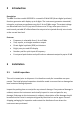
2 Introduction Description The B&K Precision model 4005DDS is a versatile 5 MHz DDS (direct digital synthesis) function generator with display up to 4 digits. The instrument generates sinusoidal, triangular, and square waveforms over the 1 Hz to 5 MHz range. The output voltage can be varied from 0 to 10 Vp-p into 50 ohms or to 20 Vp-p into open circuit. A continuously variable DC offset allows the output to be injected directly into circuits at the correct bias level.
Retain the original packing in case subsequent repackaging for return is required. Use of the original packing is essential. After the mechanical inspection, verify the contents of the shipment. The items included with the instrument are: Power cord User manual BNC to BNC cable BNC to alligator clips If the contents are incomplete, or if the instrument does not pass the specification acceptance tests, notify B&K Precision. 3.
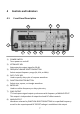
4 4.1 Controls and Indicators Front Panel Description 11 12 10 9 1 2 1) 2) 3) 4) 5) 6) 7) 8) 3 4 5 6 7 8 POWER SWITCH Turns power on and off. ATTENUATE KEY Attenuates the output signal by 20 dB. FREQUENCY RANGE SELECTION BUTTON Selects output frequency range (Hz, KHz, or MHz). DUTY CYCLE KEY Used to specify duty cycle of a square waveform. FUNCTION SELECTOR BUTTON Selects sine, square, or triangle waveform. ENTER KEY Used to confirm frequency or duty cycle entry.
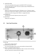
9) AMPLITUDE KNOB Controls the amplitude of the signal at the MAIN OUTPUT. Pull knob to attenuate the signal by 20 dB. This can be combined with ATTENUATE KEY for total of 40 dB attenuation. 10) DC OFFSET Applies a DC offset to the main signal. Pull knob to turn on. Clockwise rotation from center changes the DC offset in a positive direction, while counterclockwise rotation from center changes the DC offset in a negative direction. 11) NUMBER PAD Use these keys to set the frequency value or duty cycle %.
5 5.1 Operating Instructions Function Generator Output Before applying power to the unit, make sure that input voltage is correct and the ventilation holes are not blocked. Ensure the ventilation fan is working well. It is necessary to inspect the generated signal with an oscilloscope before connecting it to any electronic circuit. Hence, use of oscilloscope is mentioned in the procedure. Turn on the instrument with power on switch provided on the front panel. The display LED will light up. 1. 2. 3. 4 5.
5.2 Duty Cycle Control The DUTY CYCLE KEY can be used to alter the symmetry of a square waveform. Symmetry variation amounts to changing the duty cycle, a ratio of “high” to “low” time, effectively converting the instrument into a pulse generator. 1. 2. 3. 4. Press the DUTY CYCLE KEY and the display will blink. Use the number keys to input the duty cycle percentage value (between 20% 80% can be entered). Press the ENTER KEY to execute duty cycle adjustment.
6 Specifications 4005DDS Frequency Characteristics Waveforms Sine, Square, Triangle Range 1 Hz to 5 MHz Resolution 4 digits or 1 Hz Accuracy 0.02% (200 ppm)* Frequency Stability Output will change less than 1 ppm within a 15 minute interval and less than 2 ppm within a 24 hour interval.
SYNC Output Level ≥3V Rise Time ≤ 25 ns General AC Input 115/230 VAC, 50/60 Hz Operating Temperature 32 °F to 104 °F (0 °C to 40 °C) Humidity 10% - 80% R.H. Storage Temperature -4 °F to 158 °F (-20 °C to 70 °C) Storage Humidity 0% - 90% R.H. Dimensions (W x H x D) 11” x 4” x 11.7” (279.4 x 101.6 x 297.2 mm) Weight 5.05 lbs (2.3 kg) Instruction manual, power cord, BNC to BNC cable, BNC to alligator clips *Applies to frequencies ≥ 1 kHz.
7 Certification CE Compliant CE Declaration of Conformity The function generator meets the requirements of 2006/95/EC Low Voltage Directive and 2004/108/EC Electromagnetic Compatibility Directive. Low Voltage Directive - EN61010-1:2001 o Safety requirements for electrical equipment for measurement, control, and laboratory use. EMC Directive - EN 61000-6-2:2005 - EN 61000-6-4:2007 - EN 61326-1:2006 o Electrical equipment for measurement, control, and laboratory use.
8 Maintenance 8.1 Preventive Steps Please follow these preventive steps to ensure the proper operation of your instrument. 8.2 Never place heavy objects on the instrument. Never place a hot soldering iron on or near the instrument. Never insert wires, pins, or other metal objects into ventilation fan. Never move or pull the instrument with power cord or output lead. More importantly, never move the instrument when the power cord or output lead is connected.
8.3 Fuse Replacement If the fuse blows, the LED will not light and the instrument will not operate. Replace only with the correct value fuse. Refer to Table 1 - Fuse Table for fuse values. The fuse is located on the rear panel adjacent to the power cord receptacle. Remove the fuse holder assembly as follows: 1. Unplug the power cord from the rear of the instrument. 2. Insert a small screwdriver in the fuse holder slot (located between fuse holder and receptacle).
9 Service Information Warranty Service: Please go to the support and service section on our website at www.bkprecision.com to obtain an RMA #. Return the product in the original packaging with proof of purchase to the address below. Clearly state on the RMA the performance problem and return any leads, probes, connectors, and accessories that you are using with the device. Non-Warranty Service: Please go to the support and service section on our website at www.bkprecision.com to obtain an RMA #.
10 Limited One-Year Warranty B&K Precision Corp. warrants to the original purchaser that its products and the component parts thereof will be free from defects in workmanship and materials, for a period of one year from date of purchase. B&K Precision Corp. will, without charge, repair or replace, at its option, defective product or component parts. Returned product must be accompanied by proof of the purchase date in the form of a sales receipt. To obtain warranty coverage in the U.S.A.
(Page intentionally left blank)
22820 Savi Ranch Parkway Yorba Linda, CA 92887 www.bkprecision.com © 2014 B&K Precision Corp. Printed in Taiwan v4.14.