Model 4030 10 MHz Pulse Generator INSTRUCTION MANUAL
1 Safety Summary The following safety precautions apply to both operating and maintenance personnel and must be observed during all phases of operation, service, and repair of this instrument. Before applying power, follow the installation instructions and become familiar with the operating instructions for this instrument. GROUND THE INSTRUMENT To minimize shock hazard, the instrument chassis and cabinet must be connected to an electrical ground.
DO NOT SUBSTITUTE PARTS OR MODIFY THE INSTRUMENT Do not install substitute parts or perform any unauthorized modifications to this instrument. Return the instrument to B&K Precision for service and repair to ensure that safety features are maintained. WARNINGS AND CAUTIONS WARNING and CAUTION statements, such as the following examples, denote a hazard and appear throughout this manual. Follow all instructions contained in these statements.
Compliance Statements Disposal of Old Electrical & Electronic Equipment (Applicable in the European Union and other European countries with separate collection systems) This product is subject to Directive 2002/96/EC of the European Parliament and the Council of the European Union on waste electrical and electronic equipment (WEEE), and in jurisdictions adopting that Directive, is marked as being put on the market after August 13, 2005, and should not be disposed of as unsorted municipal waste.
Contents 1 Safety Summary ......................................................................................................... 1 2 Introduction................................................................................................................. 5 3 Installation ................................................................................................................... 5 4 5 3.1 Initial Inspection ...............................................................................
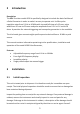
2 Introduction Description The B&K Precision model 4030 is specifically designed to include the basic facilities of a Pulse Generator in order to make it an easy to operate unit. It offers pulse repetition rates from 0.1 Hz to 10 MHz with rise and fall times of <12 nsec, pulse width from 50 nsec to 50 msec and pulse amplitude from 0.5 V to 5 V across 50 ohms. A provision for external triggering and monopulse generation is also available.
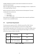
shipping packaging for inspection and contact the distributor from where the instrument was purchased. Retain the original packing in case subsequent repackaging for return is required. Use of the original packing is essential. After the mechanical inspection, verify the contents of the shipment.
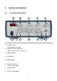
4 4.1 Controls and Indicators Front Panel Description 12 1 1) 2 11 10 9 3 4 5 3) POWER SWITCH Turns power on and off. MANUAL TRIGGER BUTTON Outputs one pulse per button press.
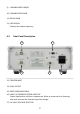
9) VARIABLE WIDTH KNOB 10) VARIABLE RATE KNOB 11) DELAY KNOB 12) LED DISPLAY Displays the output frequency 4.2 Rear Panel Description 13 17 14 15 16 13) TRIGGER INPUT 14) SYNC OUTPUT 15) EARTH GROUND SCREW 16) INPUT AC POWER SELECTOR AND FUSE Power input socket and fuse compartment. Refer to arrow mark on fuse plug and mark on panel for selected input line voltage.
5 5.1 Operating Instructions Pulse Generator Output Before applying power to the unit, make sure that input voltage is correct and the ventilation holes are not blocked. Ensure the ventilation fan is working well. It is necessary to inspect the generated signal with an oscilloscope before connecting it to any electronic circuit. Hence, use of oscilloscope is mentioned in the procedure. Turn on the instrument with power on switch provided on the front panel. The display LED will light up. 1. 2. 3. 3. 4 5.
trigger you will see a 50mS pulse (one division horizontally). You may have to push it a couple of times because sometimes the trigger pulses off the screen. To verify that the pulse is actually triggering you can hook the unit up to a counter that has a "Total" feature. Every time you push the trigger the counter will count 1 pulse. If you change your volts/division switch to 500mS and leave all the other settings the same as above, you will see the pulses very clearly.
6 Specifications 4030 Frequency Range Internal 0.1 Hz to 10 MHz in 8 decade ranges & variable adjust Internal Mode Stability 0.5% X’tal Spot Frequencies 10 MHz, 1 MHz, 100 kHz, 10 kHz, 1 kHz, 100 Hz, 10 Hz, 1 Hz X’tal Mode Stability 200 ppm Warm up Time 30 Minutes Triggering Internal 0.1 Hz to 10 MHz External 10 Hz to 10 MHz Manual One pulse out for each button press (available only for 10 MHz (100 ns) rate) Ext. Trig-Input +1 V to +10 Vp-p sine & square Trig.
Output Pulse Out 0.5 V to 5 V into 50 ohms Impedance 50 ohms Rise & Fall Time 12 nsec Terminal BNC Polarity Normal or Inverted General AC Input 115/230 VAC, 50/60 Hz, +10% Consumption 10 VA Operating Temperature 32 °F to 104 °F (0 °C to 40 °C) Humidity 10% - 80% R.H. Storage Temperature -4 °F to 158 °F (-20 °C to 70 °C) Storage Humidity 0% - 90% R.H. Dimensions (W x H x D) 10.3” x 4.4” x 12.4” (26.2 x 11.2 x 31.5 cm) Weight 5.5 lbs (2.
7 Certification CE Compliant CE Declaration of Conformity The pulse generator meets the requirements of 2006/95/EC Low Voltage Directive and 2004/108/EC Electromagnetic Compatibility Directive. Low Voltage Directive - EN61010-1:2001 o Safety requirements for electrical equipment for measurement, control, and laboratory use. EMC Directive - EN 61000-6-2:2005 - EN 61000-6-4:2007 - EN 61326-1:2006 o Electrical equipment for measurement, control, and laboratory use.
8 Maintenance 8.1 Preventive Steps Please follow these preventive steps to ensure the proper operation of your instrument. 8.2 Never place heavy objects on the instrument. Never place a hot soldering iron on or near the instrument. Never insert wires, pins, or other metal objects into ventilation fan. Never move or pull the instrument with power cord or output lead. More importantly, never move the instrument when the power cord or output lead is connected.
8.3 Fuse Replacement If the fuse blows, the LED will not light and the instrument will not operate. Replace only with the correct value fuse. Refer to Table 1 - Fuse Table for fuse values. The fuse is located on the rear panel adjacent to the power cord receptacle. Remove the fuse holder assembly as follows: 1. Unplug the power cord from the rear of the instrument. 2. Insert a small screwdriver in the fuse holder slot (located between fuse holder and receptacle).
9 Service Information Warranty Service: Please go to the support and service section on our website at www.bkprecision.com to obtain an RMA #. Return the product in the original packaging with proof of purchase to the address below. Clearly state on the RMA the performance problem and return any leads, probes, connectors, and accessories that you are using with the device. Non-Warranty Service: Please go to the support and service section on our website at www.bkprecision.com to obtain an RMA #.
10 Limited One-Year Warranty B&K Precision Corp. warrants to the original purchaser that its products and the component parts thereof will be free from defects in workmanship and materials, for a period of one year from date of purchase. B&K Precision Corp. will, without charge, repair or replace, at its option, defective product or component parts. Returned product must be accompanied by proof of the purchase date in the form of a sales receipt. To obtain warranty coverage in the U.S.A.
(Page intentionally left blank)
22820 Savi Ranch Parkway Yorba Linda, CA 92887 www.bkprecision.com © 2014 B&K Precision Corp.