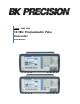
Model: 4033, 4034 50 MHz Programmable Pulse Generator USER MANUAL
Safety Summary The following safety precautions apply to both operating and maintenance personnel and must be observed during all phases of operation, service, and repair of this instrument. Before applying power, follow the installation instructions and become familiar with the operating instructions for this instrument. Failure to comply with these precautions or with specific warnings elsewhere in this manual violates safety standards of design, manufacture, and intended use of the instrument.
CAUTION: Before connecting the line cord to the AC mains, check the rear panel AC line voltage indicator. Applying a line voltage other than the indicated voltage can destroy the AC line fuses. For continued fire protection, replace fuses only with those of the specified voltage and current ratings. CAUTION: This product uses components which can be damaged by electro-static discharge (ESD).
Table of Contents Safety Summary .............................................................................................. 2 Section 1 .......................................................................................................... 6 Introduction ........................................................................................................................ 6 1.1 1.2 1.3 1.4 Introduction .................................................................................................
4.6 Instrument Identification ........................................................................................................................ 38 4.7 Instrument Reset ................................................................................................................................... 38 4.8 Self Test................................................................................................................................................. 39 4.9 Command Syntax .....................
Section 1 Introduction 1.1 Introduction This manual contains information required to operate, program, check, and maintain the 50 MHz programmable pulse generator. 1.2 Description The Model 4033 and 4034 are a high performance programmable pulse generators. The instrument generates pulse with a repetition rate to 50 MHz, width from 10 ns, variable delay, variable transition times and amplitude.
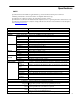
Specifications NOTE Specifications listed in manual are applicable after a powered 30 minute warm-up into a 50 Ω load All timing characteristics are measured at 50% of amplitude with fastest edge Specifications are verified according to the performance check procedures. Specifications not verified in the manual are either explanatory notes or general performance characteristics only. Specifications and information is subject to change without notice. For the most current and correct data please visit www.
PULSE FUNCTIONS Single Double One pulse at each selected period up to 50 MHz repetition rate One pair of pulses at each period up to 25 MHz repetition rate. Both pulses have the same selected width; the position of the second pulse set by the delay control. TRANSITION TIMES Range Resolution Accuracy Linearity <6 ns to 100 ms variable. Leading and trailing edges settable separately and limited to 20:1 ratio between settings into one of the following ranges: 5ns-100 ns; 50 ns-1.0 us; 500 ns-10 us; 5.
Section 2 Installation 2.1 Introduction This section contains installation information, power requirements, initial inspection and signal connections for Model 4033 and 4034. 2.2 Mechanical Inspection This instrument was carefully inspected before shipment. Upon receipt inspect the instrument for damage that might have occurred in transit. If there is damage due to shipping, file a claim with the carrier who transported the unit. The shipping and packing material should be saved if reshipment is required.
2.6 Power Requirements The model 4033 and 4034 can be operated from any source of 100-240V +/-10% AC, at a frequency from 48Hz to 66Hz. The maximum power consumption is 50 VA. WARNING THE LINE POWER VOLTAGE OF THE INSTRUMENT IS NOTED ON THE AC INPUT PLUG. TO PREVENT DAMAGE TO THE INSTRUMENT, CHECK FOR PROPER MATCH OF LINE VOLTAGE AND PROPER FUSE TYPE AND RATING. The instrument power fuse is located in the AC input plug.
2.8.1 Maintaining Pulse Fidelity Due to the extremely fast pulse rise times obtained from the instrument, special consideration must be given to preserve pulse fidelity. Even at low repetition rates, high frequency components are present in the output waveform. Use high quality coaxial cables, attenuators and terminations. Note: RG 58 type coaxial cable and typical BNC connectors exhibit impedance tolerances which may cause visible reflections.
R1 R2 = Z1 Z2, and R1 Z1 = R2 (Z2-Z1) or R1 = Z 2(Z 2 − Z 1) and R 2 = Z1 Z2 Z 2 − Z1 For example: to match a 50Ω system to a 125Ω system, Z1 equals 50Ω and Z2 equals 125Ω Therefore: R1 = 125(125 − 50) = 96.8 Ω and R2 = 50 125 = 64.6 Ω 125 − 50 Although the illustrated network provides minimum attenuation, for a purely resistive impedance-matching device, the attenuation as seen from one end does not equal that seen from the other end.
The illustrated network can be modified to provide different attenuation ratios by adding another resistor (less than R1) between Z1 and the junction of R1 and R2. When constructing such a device, the environment surrounding the components should also be designed to provide smooth transition between the impedances. Acceptable performance can be obtained with discrete components using short lead lengths; however, a full coaxial environment is preferred.
DB-9 pin 1 2 3 4 5 6 7 8 9 Name TXD RXD GND RTS CRS - Note Transmit Data Receive Data Signal ground Request to Send Clear to send - *Note: Use a Null-modem or cross over cable (pin 2 and 3 switched) in order to communicate with instrument. 2.10 RS-232 Configuration The instrument use 8 data bits, 1 stop bit, no parity and baud rate selectable from 2400 to 115K (2400, 4800, 9600, 19200, 38400, 57600, 115200). By default, the instrument is set at 19200-8-N-1.
Section 3 Operating Instructions 3.1 General Description This section describes the displays, controls and connectors of the Model 4033 and 4034 - Pulse Generators. All controls for the instrument local operation are located on the front panel. The connectors are located on both front and rear panels. 4 5 6 2 7 8 9 1 15 10 16 (Model 4034 only) 14 11 3 12 13 (Model 4033) Figure 3.1 - Front Panel View 1. 2. 3. 4.
5. 6. 7. 8. 9. 10. 11. 12. 13. 14. 15. 16. configurations (SETUP), and utility options (UTIL). Numerical Keypad - Numeric entry keys for entering values for various functions and modes Unit Setting Keys - Quick keys for setting units for frequency, time, and amplitude Rotary Knob - Used to increment/decrement numerical values or to scan through the possible selections. Cursor Keys - Used to move the cursor (when visible) to either left or right when modifying values of various parameters.
2. 3. 4. 5. 6. 7. General Waveform Display Displays the general waveform being generated in the channel. Note: Waveform shown is approximated and scaled down. It does not show the exact representation of the waveform at the output. DEL Mode Display Displays delay setting of the pulse. Alternatively, it can also display other parameters in other menu items. Menu Functions Display Displays the menu options available. Use F1-F5 keys on front panel to select the options.
Model 4033 10 9 8 1 2 Model 4034 3 12 4 5 6 7 10 9 8 11 3 5 6 7 Figure 3.3 - Back Panel View 1. 2. 3. 4. 5. Options 50 Ω - Reserved for future use. Options TTL - Reserved for future use. Trig In - Use this connector to apply an external trigger or gate signal, depending on the waveform generator setting, to the generator. Maximum input is ± 15 V. CTRL IN - Not used GPIB Interface - Use to interface with a computer via GPIB for remote communication.
6. 7. 8. 9. 10. 11. 12. RS-232 Interface - This is a standard RS-232 port used for remote interface. Null modem or cross serial cable is required to communicate with a PC via this port. Earth GND - This screw is the earth ground that is tied to the chassis. AC Power Connector - Used to connect power cable to AC line source. Fuse Box - Fuse compartment. For replacement, use T1A, 250V fuse only.
o - - PULSE o o o o MODE o o o o - - o SETUPS o o o UTIL o o o o TTL CMOS USER HIPRED | LOPRED OUTPUT LIMITS LIM OF LIM ON HILIM LOLIM PREV RISE FALL EQUAL NORM | COMPL CONT TRIG GATE BURST EXTWID MAN (Manual Trigger) INT (Internal Trigger Rate) EXT (External Trigger) PREV MAN (Manual Gate Trigger) INT (Internal Gate Trigger Rate) EXT (External Gate Trigger) PREV MAN (Manual Burst) INT (Internal Burst Rate) EXT (Burst External) NBRST (Number of Bursts) P
pulse mode is set to external width on, the value of the period may be changed but the value is not displayed, since the actual value of the period is set by the external pulse F2: WIDTH/DUTY - Selects and displays the pulse width and duty cycle. The minimum value of the width is 10ns, with the maximum value dependent on the values of the period, delay and transition times. The Duty Cycle is defined as the ratio of the pulse width to the pulse period.
Double Pulse 3.6.2 OUTPUT Menu The Output menu enables the pulse high and low levels to be set. The levels are limited by four factors: - The absolute limits are ±10 V. - The high level must be greater than the low level. - The pulse amplitude must be between 0.1 V and 10 V p-p, into 50 Ω. - The levels cannot exceed the limits as set in the OUTPUT LIMITS menu. F1: HILVL F2: LOLVL F3: PREDEF Output Menu - Selects the pulse high level voltage. - Selects the pulse low level voltage.
F5: OUTPUT LIMITS - Allows entering limits for the output levels to protect external devices connected to the unit output. Output Limits Menu F1: LIM OF – Turns off limit level protection F2: LIM ON – Turns on limit level protection F3: HILIM – Sets high limit for protection F4: LOLIM – Sets low limit for proection F5: PREV – Returns to previous menu level 3.6.3 PULSE Menu Pulse Menu F1: RISE - Selects the pulse Rise time (Leading edge). F2: FALL - Selects the pulse Fall time (Trailing edge).
The transition time range is 5 ns to 100 ms, but the value is limited to a 20:1 ratio between the transition times. In addition, both values must be within one of the following ranges: 5 ns – 100 ns 50 ns – 1 µs 500 ns – 10 µs 5 µs – 100 µs 50 µs – 1 ms 500 µs – 10 ms 5 ms – 100 ms The transition times are also limited by the values of the period, width and delay.
3.6.4 MODE Menu Selects the output trigger mode: CONT (Continuous), TRIG (Triggered), GATE (Gated), BRST (Burst) and EXTWID (External pulse). To select the output mode, press MODE, then press the function key that corresponds to the desired Mode menu option, as shown: Mode Menu F1: CONT - (Continuous) - Selects continuous output. F2: TRIG - (Triggered) – Triggers one output cycle of the selected pulse for each trigger event.
After selecting the TRIG , GATE or BURST menu, the trigger source menu is available: For TRIG and GATE mode: Trigger Menu F1: MAN - Selects manual as the trigger source. Pressing the MAN TRIG key generates the trigger. In the Gate trigger mode, the pulse is generated as long as the key is being pressed. F2: INT - Selects the internal trigger generator as the trigger source. Change the internal trigger rate displayed with the rotary input knob or numerical keys. The rate has a range of 100 ns to 99.
99.99 s, although the minimum value is limited by the value of the period in that the rate cannot be less than the period. F3: EXT - Selects the external trigger signal as the trigger source. The trigger source is supplied through the TRIG IN connector. F4: NBRST - Selects the number of burst cycles to burst. Set from 2 to 999,999 cycles. F5: LEVEL/SLOPE - Two parameters are related to external trigger source operation. These are LEVEL and SLOPE.
3.6.6 UTILITY Menu Utility Menu F1: GPIB -Selects the GPIB remote mode of operation. After selection the GPIB address can be set to any value from 1 to 31 using the rotary knob. The value is kept in a nonvolatile memory and used at power-on. The factory default address is 10. Setting the address to 31 puts the device in the offbus state (it will not respond to messages on the GPIB bus). GPIB Menu F2: RS232 -Selects the RS232 remote control mode.
time-out. F4: POWER - (Power-on default) Selects the power-on default setting. Select a value using the data keys or the rotary input knob. The selection is effective after a 20s time-out period. Select zero (0) to have the pulse generator power on with the factory default settings. Select 99 to have the pulse generator power-on with the settings it had at the last power-off.
3.10 Power-On Settings At power-on, the pulse generator performs a diagnostic self-test procedure to check itself for errors. When the pulse generator finishes the diagnostic self-test routine, it enters the local state (LOGS) and assumes power-on default settings if the POWER-ON setting is at 0. You can program the pulse generator for any settings you want at power on, as described earlier in this section.
routine finds an error, an error message is displayed. The waveform generator also displays error messages when front-panel settings are either invalid or may produce unexpected results. Error messages Message Text Setting conflict Trig rate short Empty location Calibration Error LCA load error Output overload Verify unit calibration Incorrect entry Width too high Set other level Save to Flash failed Out of range Cause Can't have this parameter set with other parameters.
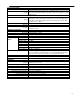
In the SINGLE or DOUBLE pulse mode the instrument defines PERIOD as the time between the 50% points on the leading edges of two consecutive trigger outputs. DELAY, in double pulse mode, is the time between the leading edges of the first and second pulse using as a reference point 50% amplitude with fastest transition times. SETTLING TIME is the interval required for the pulse level to enter and remain in the specified level ACCURACY RANGE, measured from the 90% AMPLITUDE point. 3.
Delay max Delay min = [(Period * 0.99) - Width –10 ns], but not > 9.80000 s = (Width + 10 ns) Double Pulse Transition Time Restrictions Width must be > 1.3 * Leading Edge (Delay - Width) must be > 1.3 * Trailing Edge [Period - (Delay + Width)] must be > (1.3 * Trailing Edge) Internal Trigger Burst Mode (0.99 * Trig Rate) must be > (Period * Burst Count) 3.
TRIG OUTPUT FASTEST TRANSITION TIMES SELECTED WIDTH 50% ACTUAL DELAY VARIABLE TRANSITION TIMES SELECTED 1st Corner ------------------------------- DELAY 50% 50% 3rd Corner ---------------------------------- PERIOD ------------------------------- ---------------------------- 50% Pulse Definitions – Width, Period, and Delay 50% 50% 50% WIDTH 50% 3rd Corner 50% 50% ------------------------------- 1st Corner DELAY WIDTH ------------------------------- VARIABLE TRANSITION TIMES SELECT
---------------------------- ---------------------------- ACCURACY RANGE ------------------------------------------------------90% AMPLITUDE SETTLING TIME 10% AMPLITUDE Pulse Definitions – Settling Time Section 4 Programming 4.1 Overview 4.1.1 GPIB This section provides detailed information on programming the pulse generator via the IEEE 488 bus (GPIB General Purpose Interface Bus). The pulse generator is programmable over the IEEE 488 bus, and its message protocol is compatible with IEEE 488.2.
EIA standard RS-232-C specifies the electrical characteristics and pin out of a serial communication standard for connecting "data terminal equipment" (DTE) to "data communication equipment" (DCE). Data terminal equipment is usually devices such as terminals, computers, or printers that are the final destination for data. Data communication equipment, on the other hand, is usually a modem or other device that converts the data to another form and passes it through.
In the LOCS the device may be operated from the front panel only. Its settings may be queried over the GPIB, but not changed. Commands that do not affect the signal being output by the instrument are accepted. 4.2.2 Local With Lockout State (LWLS) In the LWLS the device may be operated from the front panel only. Its settings may be queried over the GPIB, but not changed. Commands that do not affect the signal being output by the instrument are accepted.
4.5.1 The Input Buffer The device has a 128-byte long cyclic input buffer. Decoding of remote messages begins as soon as the input buffer is not empty, that is, as soon as the controller has sent at least one byte to the device. Should the input buffer be filled up by the controller faster than the device can remove the bytes and decode them, the bus handshake is not completed until room has been made for more bytes in the buffer. This prevents a fast controller from overrunning the device with data.
4.8 Self Test The *TST common query causes the device to perform a self test. This self test consists of checking the functionality of the pulse generator. 4.9 Command Syntax 4.9.1 General Command Structure The device commands are generally defined by the SCPI standard, with the exception of those instrument functions for which SCPI commands do not as yet exist. The Common Commands and Queries are defined by IEEE 488.2. The command syntax, i.e. how a command is structured, is defined by IEEE 488.2. 4.9.
This means it is not necessary to write the mnemonic into the Program Header: it is a default condition. The 'SOURCE' mnemonic, for example, is optional. Not specifying it will cause the device to search for the mnemonics in the Program Header under the Source Subsystem. For example, the period may be set by the command: :PULS:PER 1US 4.9.2.2 Program Message Header Separator The Program Header Separator is used to separate the program header from the program data.
A Program Message Unit having a colon as its first character causes the reference to return to the root. This process is defined by IEEE 488, section A.1.1. Consider the following examples: 1. The following command may be used to set the high and low levels of the pulse. Note that the LOW command is referenced to the command preceding it. The LOW mnemonic resides at the same node as the HIGH command. SOURCE:VOLTAGE:HIGH 5V;LOW 2V 2. This command sets the frequency and the high level.
is an 8-bit register whose bits correspond to those of the STB. The RQS bit in the STB is set when a bit in the STB is set, and its corresponding bit in the service request enable register is set. The service request enable register is set using the *SRE common command, and read using the *SRE? common query. 4.10.3 Standard Event Status Register The Standard Event Status Register (SESR) is defined by IEEE 488.2.
4.10.5.1 Command Errors A command error is in the range -199 to -100, and indicates that a syntax error was detected. This includes the case of an unrecognized header. The occurrence of a command error causes the CME bit (bit 5) of the Standard Event Status Register to be set.
-222 Data out of range – The parameter exceeds the absolute limits 4.10.5.3 Device-Specific Errors An error specific to the device occurred. The DDE bit (bit 3) of the Standard Event Status Register is set. Code -315 -330 -350 Description Configuration memory lost – Device memory has been lost. Check the back-up battery Self-test failed Queue overflow – Error codes have been lost due to more than 10 errors being reported without being read 4.10.5.
For Model 4034 500 Trigger rate short on channel 1 501 Trigger rate short on channel 2 510 Output overload on channel 1 511 Output overload on channel 2 "Trigger rate short" means that the period of the waveform is larger than the value of the internal trigger rate. Thus not every trigger will generate a cycle (or burst) of the waveform. 4.11 IEEE 488.2 Common Commands and Queries 4.11.1 System Data Commands The identification query command, *IDN?, enables unique identification of the device over the GPIB.
Command Type: Common Command Syntax: *OPC Examples: PULS:PER 1US;*OPC The *OPC command (and the *OPC? query described below) find use mainly when commands having relatively long execution times are executed, although all commands execute without any appreciable delay. 4.11.3.2 *OPC? - Operation Complete Query The operation complete query places an ASCII character 1 in the output queue on completion of the selected device operation.
4.11.4.3 *ESR? - Standard Event Status Register Query This query is used to read the value of the Standard Event Status Register. Reading the register clears it. COMMAND TYPE: Common Command or Query Syntax: *ESR? Response: 4.11.4.4 *PSC - Power-On Status Clear Command This command is used to control the automatic power-on clearing of certain status functions.
Response: The value of the Status Byte read with the *STB? query may differ from that read with the Serial Poll. Bit 6 of the STB will be set as long as a reason for requesting service exists, while bit 6 of the STB as read by the Serial Poll is cleared by the Serial Poll. 4.11.5 Device Trigger Commands *TRG - Trigger command This command is analogous to the IEEE 488.1 Group Execute Trigger interface message, and has the same effect.
4.12.1 SOURce Subsystem The Source Subsystem controls the frequency, voltage and pulse characteristics.
Range: Rounding: Examples: 0.1Hz to 50MHz To the resolution of the range. :FREQ 5KHZ :FREQ 5E3 QUERY Syntax: [:SOURce]:FREQuency[:CW|:FIXed]? Examples: :FREQ? Response: NR3 CONSIDERATIONS: FIXed is an alias for CW. 4.12.1.2 High Voltage Level This command is used to set the high level of the pulse. COMMAND TYPE: Setting or Query SETTING Syntax: [:SOURce]:VOLTage[:LEVel][:IMMediate]:HIGH[units] Arguments: Type: Units: Range: Rounding: Examples: NRf MV, V (default) -9.
Examples: :VOLT:LOW? Response: NRf CONSIDERATIONS: 1) The high level must be greater than the low level. 2) The difference between the levels must conform to 0.5V ≤ difference ≤ 10V 3) The low level may not be less than the low limit. 4.12.1.4 Predefined High Voltage Level This command is used to set the predefined high level of the pulse. The pulse will be set when the predefined USER levels are invoked to this high level.
4.12.1.6 Predefined Voltage Levels This command is used to set the pulse voltage levels to predefined values. Four predefined values are available as follows: CMOS: TTL: ECL: USER: High level 5V; Low level 0V High level 2.4V; Low level 0.4V High level –0.8V; Low level –1.
QUERY Syntax: [:SOURce]:VOLTage:LIMit:LOW? Examples: :VOLT:LIM:LOW? Response: NRf CONSIDERATIONS: The low limit cannot be set greater than the low level. 4.12.1.9 Pulse Period This command is used to set or query the period of the pulse.
Examples: :PULS:WIDT? Response: NRf CONSIDERATIONS: The allowed range of the width will be determined by the values of the period, delay, and transition times. 4.12.1.11 Pulse Delay This command is used to set the delay from the trigger signal to the start of the pulse in single pulse mode. Although there exists a separate command for the double pulse delay, both commands affect the same delay, and so this command will also determine the time between the two pulses in the double pulse mode.
Syntax: [:SOURce]:PULSe:DCYCle? Examples: :PULS:DCYC? 4.12.1.13 Pulse Hold This command is used to determine whether the width or the duty cycle are to be held constant when the period is changed. The duty cycle is termed to be ON when changes in the period cause changes in the width, such that the duty cycle remains constant. This state is achieved by specifying the DCYCle parameter in the HOLD command.
is generated after a programmable delay. This delay is set by either the :PULSE:DELAY or the :PULSE:DOUBLE:DELAY command. COMMAND TYPE: Setting or Query SETTING Syntax: [:SOURce]:PULSe:DOUBle[:STATe] Arguments: Type: Boolean Examples: :PULS:DOUB ON :PULS:DOUB:STAT OFF QUERY Syntax: [:SOURce]:PULSe:DOUBle[STATe]? Examples: :PULS:DOUB? Response: 0|1 4.12.1.
Type: Units: Range: Rounding: Examples: NRf S (seconds), MS (milliseconds), US (microseconds), NS nanoseconds 5NS to 10MS To current resolution :PULS:TRAN:LEAD 50NS :PULS:TRAN 85NS QUERY Syntax: [:SOURce]:PULSe:TRANsition[:LEADing]? Examples: :PULS:TRAN:LEAD? Response: NRf CONSIDERATIONS: The allowed value of the leading edge time is limited by the values of the period, width and delay.
500ns to 10us 5us to 100us 50us to 1ms 500us to 10ms 4.12.1.19 Pulse Polarity This command is used to control the polarity of the pulse, which may be normal or complemented. The COMPement and INVerted parameters are aliases: either may be used.
4.12.2 OUTPut Subsystem The Output Subsystem controls characteristics of the source’s output. The OUTPut command controls whether the output is ON or OFF. COMMAND TYPE: Setting or Query SETTING Syntax: [:OUTPut]:STATe Arguments: Type: Examples: Boolean :OUTP:STAT ON :OUTP OFF QUERY Syntax: :OUTPut[:STATe]? Response: 0|1 MODEL 4034 ONLY: To control output of channel 2, change the subsystem from :OUTP to :OUTP2. For example, to turn on output of channel, send command :OUTP2:STAT ON. 4.
Examples: BURSt :TRIG:MODE CONT :TRIG:MODE BURS QUERY Syntax: :TRIGger:MODE? Response: CONT | TRIG | GATE | BURS 4.12.3.2 Trigger Source This command is used to select the trigger source, for use in the Trigger, Gate and Burst trigger modes.
Arguments: Type: Units: Range: Rounding: Examples: NRf S (seconds), MS (milliseconds), US (microseconds), NS nanoseconds 100NS to 99.99S To current resolution :TRIG:TIM 10E-6 :TRIG:TIM 500US QUERY Syntax: :TRIGger:TIMer? Examples: :TRIG:TIM? Response: NR3 4.12.3.5 External Trigger Level Used to control the trigger level of the external trigger.
4.12.4 Status Subsystem This subsystem controls the SCPI-defined status reporting structures, which are the QUEStionable and OPERation status registers, and the error/event queue. The QUEStionable and OPERation status registers are mandated by SCPI, and so are implemented, but are not used by the hardware. No status is ever reported through them, and they are not detailed in this manual. The following shows the STATus structure used: :STATus :PRESet :QUEue [:NEXT]? 4.12.4.
4.12.5.1 GPIB Address Change This command is used to set the GPIB address. Setting the address to 31 puts the instrument in an 'offbus' state, in which it does not take part in communication over the GPIB. Communication with the instrument can be resumed only by setting the address to a suitable value from the front panel.
Type: Examples: Boolean :SYST:SEC ON :SYST:SEC OFF QUERY Syntax: :SYSTem:SECurity[:STATe]? Response: 0|1 4.12.5.5 Power-on Buffer This command is used to set the Power On Buffer setting. The instrument will power-on with the setting stored in that buffer. Setting the value to 99 will result in the instrument powering up in the state it was in before it was powered down.
4.14 SCPI Command Tree 4.14.1 Root Node Root [:SOURce] :OUTPut :TRIGger :STATus :SYSTem 4.14.
4.14.3 OUTPut Subsystem :OUTPut [:STATe] ON | OFF 4.14.4 TRIGger Subsystem :TRIGger :BURSt :TIMer :LEVel :SLOPe POS | NEG :MODE :SOURce CONT|TRIG|GATE|BURS INT | EXT | MAN | BUS 4.14.
4.14.6 SYSTem Subsystem :SYSTem :COMMunicate :ERRor? :SECurity :GPIB [:STATe]? :ADDRess ON | OFF :POBuffer :VERSion? 4.
1D 1E 1F Hex 40 41 42 43 44 45 46 47 48 49 4A 4B 4C 4D 4E 4F 50 51 52 53 54 55 56 57 58 59 5A 5B 5C 035 29 GS 3D 036 30 RS 3E 037 31 US 3F Message Definitions DCL Device Clear GET Group Execute Trigger GTL Go To Local LLO Local Lockout MLA My Listen Address Oct 100 101 102 103 104 105 106 107 110 111 112 113 114 115 116 117 120 121 122 123 124 125 126 127 130 131 132 133 134 Dec 64 65 66 67 68 69 70 71 72 73 74 75 76 77 78 79 80 81 82 83 84 85 86 87 88 89 90 91 92 ASCII @ A B C D E F G H I J K L M N O
5D 5E 5F 135 93 MTA29 136 94 ^ MTA30 137 95 _ UNT Message Definitions PPE Parallel Poll Enable PPU Parallel Poll Unconfigure SDC Selected Device Clear SPD Serial Poll Disable 7D 7E 7F SPE TCT UNL UNT 175 176 177 125 126 127 } ~ DEL MSA29,PPD MSA30,PPD Serial Poll Enable Take Control Unlisten Untalk 4.16 RS-232 Programming 4.16.1 General The INSTALLATION section of this manual describes the RS-232-C connection for the instrument.
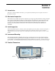
SERVICE INFORMATION Warranty Service: Please go the support and service section on our website www.bkprecision.com to obtain a RMA #. Return the product in the original packaging with proof of purchase to the address below. Clearly state on the RMA the performance problem and return any leads, probes, connectors and accessories that you are using with the device. Non-Warranty Service: Please go the support and service section on our website www.bkprecision.com to obtain a RMA #.
22820 Savi Ranch Parkway Yorba Linda, CA 92887 www.bkprecision.com © 2011 B&K Precision Corp.