Model: 4075, 4078 25 MHz Arbitrary Function Generator USER MANUAL
SERVICE INFORMATION Warranty Service: Please go the support and service section on our website www.bkprecision.com to obtain a RMA #. Return the product in the original packaging with proof of purchase to the address below. Clearly state on the RMA the performance problem and return any leads, probes, connectors and accessories that you are using with the device. Non-Warranty Service: Please go the support and service section on our website www.bkprecision.com to obtain a RMA #.
Safety Summary The following safety precautions apply to both operating and maintenance personnel and must be observed during all phases of operation, service, and repair of this instrument. Before applying power, follow the installation instructions and become familiar with the operating instructions for this instrument. Failure to comply with these precautions or with specific warnings elsewhere in this manual violates safety standards of design, manufacture, and intended use of the instrument.
CAUTION: Before connecting the line cord to the AC mains, check the rear panel AC line voltage indicator. Applying a line voltage other than the indicated voltage can destroy the AC line fuses. For continued fire protection, replace fuses only with those of the specified voltage and current ratings. CAUTION: This product uses components which can be damaged by electro-static discharge (ESD).
Table of Contents Safety Summary .............................................................................................. 3 Section 1 .......................................................................................................... 1 Introduction ........................................................................................................................ 1 1.1 1.2 1.3 1.4 Introduction .................................................................................................
4.5 Message Exchange Protocol ................................................................................................................. 36 4.6 Block Data (GPIB Only) ......................................................................................................................... 37 4.7 Instrument Identification ........................................................................................................................ 37 4.8 Instrument Reset ......................................
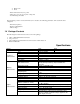
Section 1 Introduction 1.1 Introduction This manual contains information required to operate, program and test the Model 4075 and 4078 – 25 MHz DDS Arbitrary Function Generators. This section covers the instrument general description, instrument specifications and characteristics. 1.2 Description The Model 4075 and 4078 are versatile high performance arbitrary waveform generators. Arbitrary waveforms can be programmed and generated with 14 bit resolution and up to 400,000 points length.
o o Ramp down Noise - Draw a line between any two points - Clear (set to zero) any set of points or all points - Set individual point values After specifying a section of waveform memory for execution, the following parameters of the waveform can be configured: - Point rate (frequency) - Peak-to-peak amplitude - Offset voltage 1.4 Package Contents The following list of items and accessories come in the package: 1. 2. 3. 4.
Output Leakage Total Harmonic Distortion (sine) Spurious (sine) Rise/Fall Time (square, pulse) Waveform Characteristics Variable Duty Cycle Variable Symmetry Symmetry at 50% Linearity (triangle, ramp) Pulse Width (period 10 μs - 0.1 μs) Variable Edge Time (period 100 μs - 0.
Internal Trigger General Repetition Resolution Accuracy Store Memory Arbitrary Memory Dimensions Weight Power Temperature Operating Nonoperating Humidity EMC Electrical Discharge Immunity Safety Specifications 1 µs to 100 s 4 digits +0.002% 50 full panel settings at power-off 400,000 points in flash memory 8.4(213) x 3.5(88) x 12(300) inches (mm) (WxHxD) Approx. 3 kg 100 VAC-240 VAC ± 10%, 50 VA max.
Section 2 Installation 2.1 Introduction This section contains installation information, power requirements, initial inspection and signal connections for Model 4075 and 4078. 2.2 Mechanical Inspection This instrument was carefully inspected before shipment. Upon receipt inspect the instrument for damage that might have occurred in transit. If there is damage due to shipping, file a claim with the carrier who transported the unit. The shipping and packing material should be saved if reshipment is required.
2.6 Power Requirements The Model 4075 and 4078 can be operated from any source of 90 V to 264 V AC, frequency from 48 Hz to 66 Hz. The maximum power consumption is 50 VA. Use a slow blow fuse UL/CSA approved of 1 A as indicated on the rear panel of the instrument. The instrument power fuse is located in the AC input plug. To access the fuse, first disconnect the power cord and then remove the fuse cartridge. 2.7 Grounding Requirements For the safety of operating personnel, the instrument must be grounded.
2.9.1 Communication Speed The 4075 and 4078 have the capabilities of generating large arbitrary waveforms with up to 400,000 points. Due to this nature, the time it takes to transmit these large waveforms may vary depending on the baudrate and cable used for RS232 interface. As a general reference, provided below is a chart that shows the approximate amount of time it takes to download or send the waveforms of the indicated sizes at the rated baudrate speed. Number of data pts.
Section 3 Operating Instructions 3.1 General Description This section describes the displays, controls and connectors of the Model 4075 and 4078 - Function Generators. All controls for the instrument local operation are located on the front panel. The connectors are located on both front and rear panels. 4 9 10 2 5 6 7 1 12 3 14 13 8 16 15 11 7 16 Figure 3.1 - Front Panel View 1. 2. 3. Power ON-OFF Display Window FI-F4 Keys 4. 5.
6. Cursor Keys - Used to move the cursor (when visible) to either left or right when modifying values of various parameters. 7. Output ON - Controls the main output signal. The output status is ON when lid. 8. Channel - Selects the channel to configure (model 4078 only) 9. Numerical Keypad - Numeric entry keys for entering values for various functions and modes 10. Unit Setting Keys - Quick keys for setting units for frequency, time, and amplitude 11.
6. Mode Display - Displays the current mode selected. The can be continuous, trigger, burst, or gate (displayed as CONT , TRI, BURST, or GATE respectively). Refer to section 3.6.2 for details. 3.3 Front Panel Controls The front-panel controls select, display, and change parameter, function, and mode settings. They also include the keys you use to program and generate arbitrary waveform output. Refer to Figure 3.1.
generator setting, to the generator. This connector is also used when using an external signal to generate FSK under modulation menu. (See section 3.6.8 for details) 3. Marker Out - Use this connector to output a positive TTL pulse in Arbitrary waveform mode. The Marker position and width can be programmed at any desired Arbitrary locations. (See section 3.6.3 for details) 4. Sync Out - Use this connector to generate a positive TTL sync pulse output at each waveform cycle. 5.
- - o o o o SQUARE o o o o PULSE o o o o - FREQ SYM AMPL | OFST INTREF | EXTREF FREQ SYM AMPL | OFST INTREF | EXTREF FREQ PULSE FREQ | PERIOD WIDTH EQUAL EDGE LEAD | TRAIL AMPL | OFST INTCLK | EXTCLK ARB o o FREQ | RATE ARB START | LENGTH SAVE ARB • ABORT MARK • ADDR • LENGTH • ON | OFF • PREV EDIT • POINT o o o • LINE o o o • • o PREDEF o o o o MORE o o o o - MODE o o CONT TRIG BURST MAN INT • EXT ADRS DATA PREV FROM TO EXEC PREV NO | YES TYPE FROM | DATA LENGTH | SC
o - - - GATE NBRST MAN INT • GATE RATE EXT o PHASE (not available in PULSE and ARB mode) PHASE SET-ZERO PREV SWEEP (not available in PULSE and ARB mode) o ON | OFF o START | STOP o RATE o LIN | LOG MODUL o AM ON | OFF % | SHAPE MOD. FREQ EXT | INT o FM (not available in PULSE and ARB mode) ON | OFF DEV | SHAPE MOD. FREQ EXT | INT o FSK (not available in PULSE and ARB mode) ON | OFF F-HI | F-LO RATE EXT | INT UTIL o RS232< o RECALL | STORE o POWER 3.6.
In Arbitrary mode this setting defines the maximum peak-to-peak amplitude of a full-scale waveform. If the waveform does not use the full scale of data (-8191 to +8191), then its actual amplitude will be smaller.
3.6.2 MODE Key Selects the output mode: CONT (Continuous), TRIG (Triggered), GATE (Gated), and BRST (Burst). To select the output mode, press MODE, then press the function key that corresponds to the desired Mode menu option, as shown: Mode Menu F1: CONT - (Continuous) - Selects continuous output. F2: TRIG/BRST - (Triggered) - Triggers one output cycle of the selected waveform for each trigger event. - (Burst) - Triggers output N cycles for each trigger event, where N ranges from 2 to 999,999.
3.6.3 ARBITRARY Key When selected displays the following screen: Arbitrary Menu F1: FREQ/RATE F2: ARB - (Frequency) Selects and displays the frequency. Change the frequency setting using the cursor keys, rotary knob or numerical keys. If a certain wavelength can't produce the waveform at the desired frequency, the waveform generator displays an “Out of Range” error message. Displays the Point Rate (for Arbitrary Waveform only).
can be recalled when revisiting the ARB menu later on or when power cycling the instrument. Note: The 4075 and 4078 can both save multiple numbers of waveforms because the instruments have one large memory bank to store up to 400,000 points total. Essentially, the user can store multiple waves with various lengths in different locations in the memory. This can be done simply by generating each of the waveforms with different starting addresses.
Start Address Markers Length Arbitrary waveform from front panel channel output 5V 5 V TTL signal output from rear Marker Out connector 0 Marker Function Illustration F4: EDIT - Refer to section 3.6.4 below for details. **Changing one of the arbitrary parameters as start and length causes an update of the output waveform to the new parameters. When exiting the Arbitrary Menu by selecting a different waveform, a message to save the Arbitrary wave will be displayed.
3.6.4 Arbitrary EDIT Menu Enters data for creating arbitrary waveforms. You can enter data one point at a time, as a value at an address, draw a line from one point (a value at an address) to another point, create a predefined waveform, or combine these to create complex waveforms. The valid data values range is -8191 to 8191. The valid waveform memory addresses range from 1 to 400,000. The data value governs the output amplitude of that point of the waveform, scaled to the instrument output amplitude.
F1: FROM - Selects the starting point address. F2: TO - Selects the ending point address. F4: EXEC - Displays the Confirmation menu, F1:NO and F3:YES Confirmation Menu F3: PREDEF - (Predefined Waveforms) Selects one of the predefined waveforms: Sine, Triangle, Square and Noise. Displays the Predefined waveforms menu: Predefine Menu F1: TYPE - Selects the waveform Sine, Triangle, Square, Noise, Ramp up, Ramp down, exponential, Sin(x)/x, and Gaussian distribution.
value of the starting point and automatically calculated by the unit. F4: EXEC - Prompts you to confirm whether to execute the selected predefined waveform. Press NO to abort executing the predefined waveform; press YES to execute the predefined waveform. On the NOISE function a menu of ADD and NEW is prompt to select a new noise waveform or to add noise to the existing waveform.
F2: TO - Selects the address of the last point to clear. F3: ALL - Clears the whole waveform memory. Equivalent to selecting from 1 to 400,000. F4: EXEC - Prompts you to confirm whether to clear. Press NO to abort clearing, YES to clear. Protect Function. Protects (makes read-only) a section of waveform memory. F1: FROM - Selects the address of the first point to protect. F2: TO - Selects the address of the last point to protect. F3: ALL - Protects the whole waveform memory.
Utility Menu F1: GPIB - (optional) Selects the GPIB remote mode of operation. After selection the GPIB address can be set to any value from 1 to 31 using the rotary knob. The value is kept in a nonvolatile memory and used at power-on. The factory default address is 9. Setting the address to 31 puts the device in the off-bus state (it will not respond to messages on the GPIB bus). F1:RS232 - Selects the RS232 remote control mode. After selection, the baud rate can be selected as 2400, 9600, and 19200.
points of storage), users can have the freedom to store as many waveforms of different lengths as they desired in a dynamic fashion (with the limit of total points not to exceed memory capacity). Then, by using STORE and RECALL functions to save the starting address and lengths of each created arbitrary waveforms, users can quickly locate (in the memory) and output each of the different waves.
Rate. To select the sweep mode, press SWEEP, then press the function key that corresponds to the desired Sweep menu option, as shown: Sweep Menu F1: ON/OFF - Operates the sweep function, selecting between Sweep On or Off. F2: START/STOP - Defines the Sweep Start and Stop frequencies. F3: RATE - Defines the Sweep Rate. F4: LIN/LOG - Selects the Sweep Shape, LIN or LOG. Log Sweep Menu 3.6.7.
Modulation Menu F1: AM If the AM is selected, the following menu is available: AM Menu F1: ON/OFF - Selects the Modulation ON or OFF operating mode. F2: % /SHAPE - Defines the modulation depth (from 0 to 100%) and the modulation shape between SINE, TRIANGLE or SQUARE . F3: MOD-FREQ - Selects the modulation frequency, from 0.1 Hz to 20.00 KHz. F4: EXT/INT - Selects and enables the external modulation by an external signal applied to the Modulation In connector.
Modulation In connector. F3: FSK If the FSK is selected, the following menu is available: FSK Menu F1: ON/OFF - Selects the FSK ON or OFF operating mode. F2: F-HI/F-LO - Defines the High and Low frequency of the FSK. F3: RATE - Selects the rate of alternation between the low and high frequencies. F5: EXT/INT - Selects and enables the external FSK when the unit frequency is alternating between the low and high frequencies by an external signal applied to the Trig In connector. 3.
power-on default settings. Table 3-2 lists the factory default settings. You can program the waveform generator for any settings you want at power on, as described earlier in section 3.6.6. Note: OUTPUT status saved into memory cannot be recalled for power-on setting. This is a safety feature to prevent sensitive devices connected to the generator from being damaged if user accidentally turns on the unit.
Setting conflict Trig rate short Empty location SCALE too high Protected RAM Save RAM Must divide by 4 Must divide by 2 Can't have this parameter set with some other. Internal trigger rate too short for wave/burst. Attempt to restore non existent setting. Attempt to set scale too high for current dot value Attempt to write to protected RAM range. New firmware installed. Predefined wave length must be divisible by 4. Predefined wave length must be divisible by 2. 3.
* * * * * Draw lines between data points Create a predefined waveform Export waveform from software Create data points using SCPI commands Combine any of these methods The waveform’s frequency and amplitude are influenced by the number of data points and their value in the waveform. For further information on how the number of data points influence the frequency and amplitude of a waveform in execution memory, see Setting the Frequency portion (Section 3.14.3) and Setting the Amplitude portion (Section 3.
𝑟𝑎𝑡𝑒 = 1 = 1 𝜇𝑠 1000 𝑝𝑡𝑠 ∙ 1000 𝐻𝑧 EXAMPLE: Setting the Output Frequency To set the output frequency of a 1000 point waveform in execution memory to 1000 Hz, set the rate to 1 µs: ACTION KEYSTROKES Step 1. Set the output rate to 1 µs (equivalent to 1000 Hz output frequency) PARAMETER F1 :RATE 1 KHz/us 3.14.
3.14.6 Using Voltage Offset Through the offset parameter you can add a positive or negative DC level to the output waveform. To set voltage offset: 1. Press Waveform to display the menu. 2. Press F3 :OFST to display the offset setting. 3. Use the rotary input knob or the numerical keys to set the voltage offset. To turn the voltage offset OFF, repeat the steps above, but set the offset voltage level to 0. 3.14.
Section 4 Programming 4.1 Overview 4.1.1 GPIB This section provides detailed information on programming the 4075 and 4078 via the IEEE 488 bus (referred to from now as the GPIB - General Purpose Interface Bus). The 4075 and 4078 are programmable over the IEEE 488.1 bus, and its message protocol is compatible with IEEE 488.2. The device command set is compatible with the SCPI 1992.0 standard. The command syntax as defined by the IEEE 488.2 and SCPI standards is briefly explained in the following sections.
The instrument accepts a carriage return (CR) as an end of string (EOS) terminator and sends both a CR and LF as the EOS terminator. 4.2 Device State The device may be in one of the four possible states described below. The transition between states is defined by IEEE 488.1. 4.2.1 Local State (LOCS) In the LOCS the device may be operated from the front panel only. Its settings may be queried over the GPIB, but not changed. Commands that do not affect the signal being output by the instrument are accepted.
4.5 Message Exchange Protocol The device decodes messages using the Message Exchange Protocol (MEP) defined in IEEE 488.2. The following functions implemented in the MEP must be considered: 4.5.1 The Input Buffer The device has a 256-byte long cyclic input buffer. Decoding of remote messages begins as soon as the input buffer is not empty, that is, as soon as the controller has sent at least one byte to the device.
current frequency out of range. c) The commands to set modulation, modulation source and the function are inter-related. FM and FSK are not available for ARB function. External source of modulation can be active for either FM or AM but not both. FSK and FM cannot be active at the same time. d) Sweep start and sweep stop frequencies must be distanced more than the minimum allowed for sweep to function correctly. 4.
c) LF being sent with EOI true. The Program Message Unit can be divided into three sections as follows: a) Program Header The Program Header represents the operation to be performed, and consists of ASCII character mnemonics. Two types of Program Headers are used in the 4075 & 4078: Instrument-control headers and Common Command and Query headers. A Program Header may consist of more than one mnemonic, in which case the mnemonics are separated from each other by the colon (':').
or numeric. A numeric value is rounded to an integer. A non-zero result is interpreted as 1 (ON), and a zero result as 0 (OFF). Queries return the values 0 or 1. iii) NRf This is a decimal numeric data type, where NR1 indicates an integer number, NR2 indicates a fixed point real number, and NR3 indicates a floating point real number. iv) Expression data An expression is contained in parentheses (...). This data type is used only with the STATus:QUEue:ENABle command.
- # - 0 – 8-bit byte – LF^EOI Some Program Message Units either require, or can accept, more than one data element. Program data elements are separated from each other by the Program Data Separator. It is defined as optional whitespace characters followed by a comma (','), which in turn is followed by optional whitespace characters. There are two types of Program Message Units: Command Message Units and Query Message Units.
Common Commands may be inserted in the Program Message without affecting the instrument-control command reference. For example, SOURCE:VOLTAGE:AMPLITUDE 4V;*ESE 255;OFFSET 2V FOR MODEL 4078 ONLY: Exclusively for the model 4078 with multiple channels, the selection of which channel to use is achieved through the use of a numeric suffix indicating the channel, attached to the root level mnemonic. Four root level mnemonics are channel-dependent, and these are SOURce, TRIGger, OUTPut and ARBitrary.
4.11.2 Service Request Enabling Service request enabling allows the user to select which Status Byte summary messages may cause the device to actively request service. This is achieved using the Service Request Enable Register, which is an 8-bit register whose bits correspond to those of the STB. The RQS bit in the STB is set when a bit in the STB is set, and its corresponding bit in the service request enable register is set.
The error message is returned in the form ,"" A table of error numbers and their descriptions is presented here. No error reported 0 No error Command Errors A command error is in the range -199 to -100, and indicates that a syntax error was detected. This includes the case of an unrecognized header. The occurrence of a command error causes the CME bit (bit 5) of the Standard Event Status Register to be set.
-178 Expression data not allowed Execution Errors An execution error indicates that the device could not execute a syntactically correct command, either since the data were out of the instrument's range, or due to a device condition. The EXE bit (bit 4) of the Standard Event Status Register is set on occurrence of an execution error. -200 -201 -211 -220 -221 -222 -223 -224 -258 Execution error An attempt was made to RECALL the contents of an uninitialized stored setting buffer. Invalid while in local.
System Events System events have positive valued codes. They are not defined by SCPI, but are specific to the instrument. Sending the :STATus:PRESet command will disable these events from being reported. 401 402 Power on Operation complete The *OPC command has been executed. Warnings The execution of some commands might cause an undesirable instrument state. The commands are executed, but a warning is issued. Sending the :STATus:PRESet command disables reporting of warnings.
Response: B&K, MODEL 4078,0,V1.03 b) *OPT? - Option identification query The Option Identification Query is used to identify device options over the system interface. This query should always be the last in a program message. Command Type: Syntax: Response : Common Query *OPT? No option available. 4.12.2 Internal Operation Commands a) *RST - Reset command The Reset command performs a device reset. It causes the device to return to the factory default power up state.
Syntax: Response: Example *OPC? ASCII character 1 FREQ 1KHz;*OPC? c) *WAI - Wait-to-continue command This command is intended for use with overlapped commands. No commands in the instrument are overlapped, and so this command has no effect. Type: Syntax: Common Command *WAI 4.12.4 Status and Event Commands a) *CLS - Clear status The clear status command clears the SESR and Error Queue status data structures.
Syntax: *PSC? Response: ASCII 0 for OFF ASCII 1 for ON When set to ON (1), the Service Request Enable Register and the Standard Event Status Enable Register are cleared on power-on. e) *SRE - Service request enable command This command sets the Service Request Enable Register bits. Arguments Type: NRf Range: 0 to 255. Non integer arguments are rounded before execution. The value of bit 6 is ignored, and is set always to zero.
Arguments Type Range 0 to 49. Non integer values are rounded before execution Type: Syntax: Example: Common Command *RCL *RCL 0 (Recall default state) *RCL 49 Stored setting location 49 stores the last instrument setting before power down. b) *SAV - Save instrument state This command is used to store the current instrument state in the specified memory location. Arguments Type: Range: 1 to 49.
:AM [:STATe] :DEPTh :SHAPe SINusoid|SQUare|TRIangle :FREQuency :SOURce INTernal |EXTernal :FM [:STATe] :DEViation :SHAPe SINusoid|SQUare|TRIangle :FREQuency :SOURce INTernal |EXTernal :FSK [:STATe] :LOWFrequency :HIFrequency :RATE :SOURce INTernal |EXTernal :SWEep :STATe :SPACing :TIME :STARt :STOP :P
Query Syntax: Examples: Response: [:SOURce]:FREQuency[:CW]?[MAXimum|MINimum] :FREQ? :FREQ? MAX NR3 Considerations: 1) The MIN | MAX arguments should be used only in a Program Message that does NOT contain Program Message Units specifying Arbitrary Point Rate or Wavelength, since the MAXimum or MINimum value is calculated at the time the command is parsed. 2) The MIN and MAX arguments refer to currently settable minimum or maximum. 3) FIXed is alias for CW. 4.13.1.
Arguments Type: Units: Range: Rounding: Command Type: Setting Syntax: Examples: Query Syntax: Examples: Response: Considerations: Numeric V, mV 10mV to 4.99V to 10mV Setting or Query [:SOURce]:VOLTage:OFFSet[units] [:SOURce]:VOLTage:OFFSetMINimum|MAXimum :VOLT:OFFS 2.5 :VOLT:OFFS 2.5V :VOLT:OFFS MAX [:SOURce]:VOLTage:OFFSet?[MINimum|MAXimum] :VOLT:OFFS? :VOLT:OFFS? MAX NR2 1) The MAXimum offset is dependent on the amplitude.
Syntax: [:SOURce]:FUNCtion[:SHAPe]? Examples: :FUNC? Response: SIN|TRI|SQU|ARB|PUL Considerations: The following functions are available: Sinusoid, Square, TRIangle, ARBitrary, PULse 4.13.1.6 Point Rate :SOURce:PRATe This command is used to set the point rate. It is coupled with the frequency of the waveform by the relation Frequency = 1/(Point Rate * Wavelength) Thus changing the point rate will result in a change in frequency.
Rounding: to integer Command Type: Setting or Query Setting Syntax: :SOURce:AM:DEPTh :SOURce:AM:DEPThMINimum|MAXimum Examples: AM:DEPTh 50 Query Syntax: AM:DEPTh?[MINimum|MAXimum] Response: NR3 4.13.1.7.
Examples: Query Syntax: Response: AM:SOUR INT AM:SOUR EXT [:SOURce]:AM:SOURce? INT|EXT 4.13.1.8 FM modulation The following commands control the FM modulation: 4.13.1.8.1 FM STATe This command activates or deactivates FM modulation: Arguments Type: Boolean Command Type: Setting or Query Setting Syntax: [:SOURce:]FM[:STATe]ON|1|OFF|0 Examples: FM:STAT ON FM OFF Query Syntax: [:SOURce:]FM[:STATe]? Response: 0|1 4.13.1.8.
Syntax: Response: [:SOURce:]FM:SHAPe? SIN|TRI|SQU 4.13.1.8.4 FM FREQuency This command sets the FM modulating waveform frequency Arguments Type: Numeric. Units: MHz, KHz, Hz (default) Range: Fmax = 20 KHz Fmin = 0.01 Hz Rounding: The value is rounded to 4 digits.
4.13.1.9.2 FSK LOWFrequency This command sets the lower of the two frequencies used in FSK modulation. Arguments Type: Numeric. Units: MHz, KHz, Hz (default) Range: The whole frequency range of the current function. Rounding: The value is rounded to 4 digits.
Examples: Query Syntax: Examples: Response: FSK:RATE FSK:RATE FSK:RATE FSK:RATE 5KHZ 5E3 MAXIMUM MIN [:SOURce]:FSK:RATE ?[MAXimum|MINimum] FSK:RATE ? FSK:RATE ? MAX NR3 4.13.1.9.5 FSK SOURce This command selects the FSK modulation source as either internal (then the above settings are effective) or external (and then the external waveform determines the frequency of modulation).
4.13.1.10.3 Sweep TIME This command sets the time for one complete sweep: Arguments Type: Numeric Units: S, mS, uS, nS Range: 20mS to 500S Rounding: to 4 digits Command Type: Setting or Query Setting Syntax: [:SOURce:]SWEEP:TIME
Query Syntax: Examples: Response: [:SOURce:]SWEEP:STOP?[MAXimum|MINimum] SWEEP:STOP ? SWEEP:STOP ? MAX NR3 4.13.1.
Syntax: Response: [:SOURce:] PULse: WIDth?[MINimum|MAXimum] NR3 4.13.1.12.3 PULse EDGe This command sets both rising and falling edge of the pulse to the specified value.
This command is used to set the duty-cycle of the square wave or the symmetry of triangular wave. The value is given in percent . Arguments Type: Units: Range: Rounding: Command Type: Setting Syntax: Query Syntax: Response: Numeric None (percent implied) 20 to 80 to integer Setting or Query :SOURce: DCYCle :SOURce: DCYCle MINimum|MAXimum :SOURce: DCYCle?[MINimum|MAXimum] NR3 4.13.2 OUTPut Subsystem The Output Subsystem controls characteristics of the source's output.
:SOURce Note: For model 4078, nothing changes in the commands above to control channel 1. But for channel 2, change :TRIG to :TRIG2. For example, to change channel 2 mode to gate, send the command: TRIG2:MODE GATE. 4.13.3.1 Trigger Mode :TRIGger:MODE This command is used to set the trigger mode. It is not a standard SCPI command.
Arguments Type: Range: Rounding: Command Type: Setting Syntax Examples Query Syntax: Response: Examples: Numeric 1 to 999999 to integer value Setting or Query :TRIGger:BURSt :TRIG:BURS 100 :TRIG:BURS MAXIMUM :TRIGger:BURSt?[MAXimum|MINimum] NR1 :TRIG:BURST? :TRIG:BURS? MAX 4.13.3.4 Internal Trigger Rate :TRIGger:TIMer Sets the rate of the internal trigger.
:ADDRess :DATA | :DRAW , :CLEar , :COPY ,, :PROTect [:RANGe] , :STATe :PREDefined ,,, :STARt :LENGth :MARKer [:ADDRess] :STATe :LENGth :SAVe Note: For model 4078, nothing changes in the commands above to control channel 1.
This command sets the current address of the waveform. It is used to determine where arbitrary data are to be written. Use this command when querying data points using ARB:DATA? After generating data points. Arguments Type: Range: Rounding: Command Type: Setting Syntax: Examples: Query Syntax: Response: Numeric 1 to 400,000 to integer value Setting or Query :ARBitrary:ADDRess :ARBitrary:ADDRessMINimum|MAXimum :ARB:ADDR 100 :ARBitrary:ADDRess?[MINimum|MAXimum] NR1 4.13.4.
4.13.4.4 Line Draw :ARBitrary:DRAW , This command is used to generate a straight line between two points in the arbitrary waveform memory. Arguments Type: Range: Rounding: Command Type: Setting Syntax: Example: Considerations: Numeric. 1 to 400,000 to integer value Setting only :ARBitrary:DRAW, :ARB:DRAW 1,1000 1) The value of the data at the start and end points must first be set by the user, using the :ARB:DATA command.
2) The end address must be greater than the start address. 4.13.4.6 Copy :ARBitrary:COPY ,, This command is used to copy a section of the waveform to a different location in waveform memory. Arguments Type: Range: Rounding: Command Type: Setting Syntax: Example: Considerations: NRf 1 to 400,000 to integer value Setting only :ARBitrary:COPY,, :ARB:COPY 1,1000,1001 1) The destination range cannot overlap with protected memory.
Example: Query Syntax: Response: :ARB:PROT:STAT ON :ARBitrary:PROTect:STATe? 0|1 4.13.4.9 Predefined Waveforms :ARB:PRED ,,, This command is used to load the waveform memory with a specific type of waveform.
4.13.4.10 Start Address :ARBitrary:STARt This command sets the start address of the waveform to be run.
Setting Syntax: Examples: Query Syntax: Example: Response: Considerations: :ARBitrary:MARKer[:ADDRess] :ARB:MARK 45 :ARBitrary:MARKer[:ADDRess]? :ARB:MARK? Marker address in NR1 format. The marker is only output if its address is within the range of addresses currently being run. 4.13.4.13 Marker Length :ARBitrary:MARKer:LENGth This command is used to set the marker length. The maximum allowed length of marker is 4000.
4.13.5 Status Subsystem This subsystem controls the SCPI-defined status reporting structures, which are the QUEStionable and OPERation status registers, and the error/event queue. The OPERation status registers are mandated by SCPI, and so are implemented, but are not used by the hardware. No status is ever reported through them, and they are not detailed in this manual.
that were enabled before the last power down. Type: Expression The expression data takes the form (NRf|[{,NRf|}]) where NRf represents an error number. Entries are rounded to integer values. An is defined as NRf:NRf The first number in a range MUST be less than the second. Up to 6 ranges may be specified using one :ENABle command, representing the 6 ranges of errors/events. The ranges are then separated from each other by Program Data Separators (comma).
:STATus:QUEstionable:CONDition? This query is used to read the condition register. Command Type: Query only Query Syntax: :STATus:QUES:COND? Response: NR1 4.13.5.4.2 Positive Transition Filter :STAT:QUES:PTR This command is used to set and query the value of the positive transition filter. Arguments Type: Range: Command Type: Setting Syntax: Examples: Query Syntax: Response: NRf 0 to 131,072. Non integer arguments are rounded before execution.
This command is used to set and query the value of the enable register. Arguments Type: Range: Command Type: Setting Syntax: Examples: Query Syntax: Response: NRf 0 to 131,072. Non integer arguments are rounded before execution. Setting or Query :STAT:QUES:ENAB :STAT:QUES:ENAB 2048 :STAT:QUES:ENAB? NR1 4.13.6 System Subsystem The SYSTem subsystem collects the functions that are not related to instrument performance.
:SYSTem:ERRor? This query returns the first entry in the error queue, and removes that entry from the queue. Its function is identical to that of the :STATus:QUEue:NEXT? query. Command Type: Query only Query Syntax: :SYSTem:ERRor? Response: , "" 4.13.6.3 SCPI Version :SYSTem:VERSion? This query is used to read the SCPI version to which the instrument complies. Command Type: Query only Query Syntax; :SYSTem:VERSion? Response: 1992.0 (NR2 format) 4.13.6.
Syntax: Response: :SYSTem:POBuffer?[MINimum|MAXimum] Power-on buffer in NR1 format 4.14 IEEE 488.1 Interface Messages 4.14.1 GET - Group Execute Trigger The GET is used by the AWG as a trigger when it is in either the TRIGGER, GATE or BURST modes, with the trigger source set to BUS. It has the same effect as the *TRG common command. 4.14.2 DCL - Device Clear In response to the DCL, the AWG does the following: a) Clears the input buffer and the output queue. b) Resets the Message Processing Functions.
4.15 SCPI Command Tree 4.15.1 Root Node Root [:SOURce] :OUTPut :TRIGger :ARBitrary :STATus :SYSTem 4.15.
4.15.4 :TRIGger Subsystem :TRIGger :MODE CONT | TRIG | GATE | BURS :BURSt :SOURce :TIMer INT | EXT | MAN | BUS :PRATe :ADDRess :DATA :STARt 4.15.
4.15.6 :STATus Subsystem :STATus :OPERation [:EVENt]? :CONDtion? :ENABle :PTRansition :NTRansition :QUEStionable [:EVENt]? :CONDtion? :ENABle :PTRansition :PRESet :NTRansition :QUEue [:NEXT]? :ENABle 4.15.
ASCII and GPIB Code Chart Hex 00 01 02 03 04 05 06 07 08 09 0A 0B 0C 0D 0E 0F 10 11 12 13 14 15 16 17 18 19 1A 1B 1C 1D 1E 1F Oct Dec ASCII Msg 000 0 NUL 001 1 SOH GTL 002 2 STX 003 3 ETX 004 4 EOT SDC 005 5 ENQ PPC 006 6 ACK 007 7 BEL 010 8 BS GET 011 9 HT TCT 012 10 LF 013 11 VT 014 12 FF 015 13 CR 016 14 SO 017 15 SI 020 16 DLE 021 17 DC1 LLO 022 18 DC2 023 19 DC3 024 20 DC4 DCL 025 21 NAK PPU 026 22 SYN 027 23 ETB 030 24 CAN SPE 031 25 EM SPD 032 26 SUB 033 27 ESC 034 28 FS 035 29 GS 036 30 RS 037 31
Hex 40 41 42 43 44 45 46 47 48 49 4A 4B 4C 4D 4E 4F 50 51 52 53 54 55 56 57 58 59 5A 5B 5C 5D 5E 5F Oct Dec ASCII Msg 100 64 @ MTA0 101 65 A MTA1 102 66 B MTA2 103 67 C MTA3 104 68 D MTA4 105 69 E MTA5 106 70 F MTA6 107 71 G MTA7 110 72 H MTA8 111 73 I MTA9 112 74 J MTA10 113 75 K MTA11 114 76 L MTA12 115 77 M MTA13 116 78 N MTA14 117 79 O MTA15 120 80 P MTA16 121 81 Q MTA17 122 82 R MTA18 123 83 S MTA19 124 84 T MTA20 125 85 U MTA21 126 86 V MTA22 127 87 W MTA23 130 88 X MTA24 131 89 Y MTA25 132 90 Z MTA2
4.16 Block Transfer (GPIB only) Arbitrary waveform data sent in IEEE488.2 arbitrary block format may take two forms: the definite form and the indefinite form. The essential difference between these forms is that the definite form contains a byte count, while the indefinite form does not. In both cases, the format of the command is :ARB:DATA. The represents the arbitrary waveform data. This field consists of 8 bit bytes sent in hexadecimal form.
4.17 GPIB Communication Protocol (for models 4075GPIB & 4078GPIB) 4.17.1 General This appendix describes the effects of interface messages on waveform generator operation and uses abbreviations from the IEEE Standard 488.1-1987. 4.17.2 Responses to IEEE-488.1 Interface Messages Interface messages and the effects of those messages on the instrument interface functions are defined in IEEE Standard 488.1-1987. Where appropriate, the GPIB code is listed, in decimal.
SPE-Serial Poll Enable (24 with ATN) The SPE message generates output serial poll status bytes when talk-addressed. SPD-Serial Poll Disable (25 with ATN) The SPD message switches back to generating output data from the Output Buffer. MLA-My Listen Address (GPIB Address + 32) MTA-My Talk Address (GPIB Address + 64) The instrument GPIB primary address establishes the listen and talk addresses. To see the current GPIB primary address, press SPECIAL and then F1:SYS on the front panel.
Local State (LOCS) When in a local state (LOCS), you control the settings through the front-panel controls. In addition, only GPIB query commands are executed. All other GPIB commandsִsetting and operationalִprompt and error since those commands are under front-panel (local) control. NOTE The waveform generator can be in either Local State (LOCS) or Remote State (REMS) when the it receives the Local Lockout (LLO) interface message.
Basic Talker T6 Basic Listener Service Request Remote-Local Parallel Poll Device Clear Device Trigger Controller Electrical Interface L4 SR1 RL1 PP0 DC1 DT1 C0 E2 Responds to Serial Poll, Untalk if My Listen Address (MLA) is received Unlisten if My Talk Address (MTA) is received Complete capability Complete capability, including Local Lockout (LLO) Does not respond to Parallel Poll Complete capability Complete capability No controller functions Three-state drive capability
Section 5 Performance Check Procedures 5.1 Introduction This section provides the procedure for checking the electrical performance requirements of the Model 4075 and 4078 Arbitrary Waveform Generators, as listed in instrument Operating Manual Section 1: “ Specifications”. If the waveform generator fails to meet these checks, then you should perform the adjustment procedure. Adjustment procedures are available on a separate document.
5.3 Performance Tests The following tests verify that the waveform generator operates and meets specifications. Perform the tests after a warm-up period of 30 minutes at an ambient temperature of 22°C ± 3°C. You can use these tests for periodic inspection and for inspection after repair. NOTE 5.3.1 In the following procedures, all test conditions for the waveform generator are power-up conditions with output ON, unless otherwise specified. Frequency Accuracy Specification: 0.
Amplitude setting Minimum reading RMS Maximum reading RMS 10Vp-p 3.499V 3.572V 5Vp-p 1.749V 1.786V 3Vp-p 1.049V 1.072V 1Vp-p 0.349V 0.358V 100mVp-p 34 mV 37 mV 50mVp-p 17 mV 19 mV DVM reading RMS 5. Set the unit to generate a SQUARE wave with 1KHz frequency. 6. CHECK that the measured voltages on the DVM at 10Vp-p, 5Vp-p, 3Vp-p, 1Vp-p, 100 mVp-p and 50mVp-p are in the accuracy range: Amplitude setting Minimum reading RMS Maximum reading RMS 10Vp-p 4.949V 5.051V 5Vp-p 2.474V 2.
- Select OUT ON 8. CHECK that the measured voltages on the DVM at 10Vp-p, 5Vp-p, 3Vp-p, 1Vp-p, 100 mVp-p and 50mVp-p are in the accuracy range: Amplitude setting Minimum reading RMS Maximum reading RMS 10Vp-p 3.499V 3.572V 5Vp-p 1.749V 1.786V 3Vp-p 1.049V 1.072V 1Vp-p 0.349V 0.358V 100mVp-p 34 mV 37 mV 50mVp-p 17 mV 19 mV DVM reading RMS 5.3.3 Offset Accuracy Specification: ±1% of programmed value ±10mV, into 50 ohm Procedure: 1.
7.13 Connect the OUTPUT connector to the distortion analyzer using a 50 ohm coaxial cable and a 50 ohm feedthrough termination. 7.14 Set the unit to generate a sine waveform with 1KHz frequency and 10Vp-p. 7.15 Set the distortion analyzer to measure distortion in dB and select RMS response. 7.16 CHECK for a reading of more than -65 dB. 5.3.5 Square Transition Times Specification: < 6 ns (10% to 90%) at 10Vp-p into 50 ohms. Procedure: 1.
4. Set the external function generator for a square wave output from 0V to 2V at 200 Hz. 5. Connect the function generator output to the unit TRIG IN connector. 6. Set the waveform generator: Step 1. Set the output mode to triggered Step 2. Set the trigger source to internal MODE F2 - TRIG F2 - INT 7. CHECK-Verify that the oscilloscope displays one cycle of sine wave per trigger event. 8. Set the waveform generator: Set the output mode to external trigger MODE F2-TRIG F3 - EXT 9.
- Select F2 – ARB - Select F4 – EDIT - Select F3 – PREDEF - Select F2 – FROM, press key 1 and ENTER - Select F2 – DATA, press key 0 and ENTER - Select F4 – EXEC - Select F3 – YES - Select ARB - Select F2 – ARB - Select F3 – MARK - Select F3 – ON 7. 5.3.8 CHECK for a pulse with a 1us width and with 0V and >4V levels on the oscilloscope. External Modulation Specification: 5 Vp-p for 100% AM modulation.
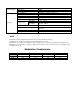
Performance Tests Results Setting Minimum reading Frequency DDS 1 MHz Maximum reading 999980 Hz 1000020 Hz 999950 Hz 1000050 Hz 3.499V 3.572V 5Vp-p 1.749V 1.786V 3Vp-p 1.049V 1.072V 1Vp-p 0.349V 0.358V 100mVp-p 34 mV 37 mV 50mVp-p 17 mV 19 mV Square Amplitude 10Vp-p 4.949V 5.051V 5Vp-p 2.474V 2.526V 3Vp-p 1.484V 1.516V 1Vp-p 0.494V 0.51 100mVp-p 49 mV 52 mV 50mVp-p 24 mV 26 mV ARB Amplitude 10Vp-p 3.499V 3.572V 5Vp-p 1.749V 1.786V 3Vp-p 1.049V 1.
80% 79.00% 80.00% Yes Operating Modes: No Triggered Burst External Trigger Sync Output Marker Output Reference Output External Modulation RS-232 .
22820 Savi Ranch Parkway Yorba Linda, CA 92887 www.bkprecision.