
User Manual


34
Emergency Shut Off
In the case where an emergency shut off to the output of the power supply is required,
SHUT_OFF (pin 15) and DGND (pin 1) is used.
To shut off, connect/short Pin 15 and Pin 1 together. This will bypass the analog control of the
output state and disable (OFF) the output. In this case, pin 14 and pin 1 will need to be
disconnected/opened from each other and reconnected to enable output again.
Power Supply Status
The power supply status can be monitored using POWER_OK (pin 16) output and DGND (pin 1).
During normal operating conditions, this pin will output 5 VDC. If OTP condition or other
abnormalities occur, this pin will output 0 VDC.
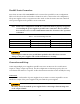
Monitoring Operation Mode
The operation mode of the power supply can be monitored using CV_CC+ (pin 18) and CV_CC-
(pin 19) output pins.
CV Mode – Pin 18 and Pin 19 will output 5 V DC.
CC Mode – Pin 18 and Pin 19 will output –5 V DC.
OFF – Pin 18 and Pin 19 will output 0 VDC.
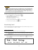
Control Output Settings
The voltage and current output settings can be configured using an external source connected
to VPRG (pin 20) and Ground (pin 8) for voltage and IPRG (pin 22) and Ground (pin 10) for
current.
Follow the instructions in the previous sections for configuration and setup.
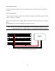
Monitor Output Settings
The voltage and current output can be monitored using VMON (pin 23) and Ground (pin 11) for
voltage and IMON (pin 24) and Ground (pin 12) for current.
Follow the instructions in the previous sections for configuration of the voltage scale to use for
monitoring. The scale can be selected between 0 – 10 VDC or 0 – 5 VDC to reflect 0 – 100% of
voltage or current output.