
User Manual


25
2. Use a small flat blade screwdriver to loosen the wire connection
connected between Vo+ and S+ and S- and Vo-.
3. Connect the S+ to the DUT’s positive (+) terminal, and connect
the S- to the DUT’s negative (-) terminal.
4. Do not connect any wires to Vo+ and Vo- terminals.
5. Power ON the power supply, and then configure and enable the
output. The setup should look like the figure above.
DO NOT at any time disconnect the wires from the Vs+ and Vs-
terminals to the DUT while output is enabled (ON). Doing so may
damage the power supply and cause unstable output.
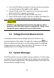
3.3 Voltage/Current Measurement
The display will show the set voltage and current values or the
measured values of the output. To toggle this reading, press key.
When the Meter LED indicator is on, the display shows the measured
voltage and current values. When the Meter LED indicator is off, the
display shows the set voltage and current values.
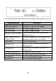
3.4 System Messages
The PVS has built-in sensors to detect system conditions. If a fault status
occurred, the error message will show on the display and automatically
protect the power supply output. The following display occurs when the
fan has failed or stopped turning: