
User Manual


40
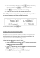
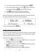
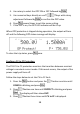
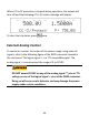
When CC to CV protection is tripped during operation, the output will
turn off and the following CC to CV status message will display:
To clear the trip status, press once.
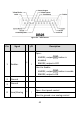
External Analog Control
To control or monitor the output of the power supply using external
signals, refer to the following figure of the DB25 connector located in
the rear panel. The logical signal ○
L
is a TTL compatible signal. The
analog signal ○
A
cannot exceed the range of 0 to 12VDC.
DO NOT exceed 12VDC on any of the analog signal ○
A
pins or TTL
voltage on any of the logical signal ○
L pins
of the DB25 connector.
Doing so will cause erratic behavior and may damage the power
supply under certain conditions.