
User Manual


51
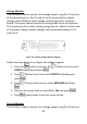
of the ground pins (i.e. Pin 23), which can be connected to a digital
voltage meter (DVM) or other voltage monitoring device, as shown
below. The output control must be in analog mode to use this function.
The monitoring of the output voltage range (which reflects 0 to full scale
of the power supply’s output voltage) can be selected between 0-5 V
and 0-10 V.
Figure 3.9 - Analog Current Monitor Diagram
Follow the steps below to configure the voltage program.
1. Press the button and press the button one time until
CONFIG is blinking and press .
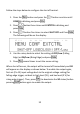
2. Press button three times until EXTCTRL is blinking and
press .
3. Press button four times to select MON RNG and Press
.
4. Now use the rotary knob to select 5V or 10V and press .
5. Press several times to exit the menu setting.
Shut Off Control
Shut off control allows Pin 15 of the DB25 interface to be used to shut
off the power supply’s output, which is controlled by an input trigger
signal. The output shuts off with the falling or rising edge of the trigger.