Instruction Manual 1 Model 1785B, 1786B, 1787B & 1788 Programmable DC Power Supplies
Content Quick Reference ..............................................................................................................................3 About your safety......................................................................................................................3 General information...........................................................................................................3 Protection from electric shock ................................................................
Quick Reference About your safety Pease review the following safety precautions before operating our equipment. General information The following safety precautions should be observed before using this product and any associated instrumentations. Although some instruments and accessories would be used with non-hazardous voltages, there are situations where hazardous conditions may be present.
Certification and Warranty Certification We certify that this product met its published specifications at time of shipment from the factory. Introduction The 1785B - 1788 Series power supplies are high performance single-output programmable DC power supplies with communication interface. The combination of bench-top and system features in these power supplies provides versatile solutions for your design and test requirements.
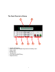
The Front Panel at a Glance 2 1 3 ? ? ? ? ? ? ? 4 5 6 10 digits VFD display Status information for operating mode and working status Power switch Number keys Function keys UP/DOWN and ENTER key Output terminals 5 7
Function keys description V-set I-set Save Recall Menu Out on/off Set the output voltage value Set the current value Save the present settings to a specified register location(1~16) Recall a saved settings from location ‘‘1’’through ‘‘16’ Menu function to set related parameters of the power supply Output ON/OFF, to enable/disable the output Menu description Menu >MAX VOLT >INIT OUT >INIT VOL >KEY SOUN Set the maximum output voltage value Initiate the output state to ON or not Initiate the output v
ON Oh CV Output ON Overheat protection state The power supply is in constant voltage mode. CC The power supply is in constant current mode.
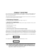
Chapter 1 Quick Start One of the first things you will want to do with your power supply is to become acquainted with the front panel. The exercises in this chapter prepare the power supply for use and help you get familiar with some of its front-panel operations. This chapter is intended for both the experienced and the inexperienced user because it calls attention to certain checks that should be made prior to operation. 1.
1.2 Output Checkout The following procedures check to ensure that the power supply develops its rated outputs and properly responds to operation from the front panel. 1.2.1 Voltage Output Checkout The following steps verify basic voltage functions without load. 1. Turn on the power supply. 2. Enable the outputs. Press Out on/off key to let the ON annunciator and the CV annunciator turn on to light.
zero. 7. Ensure that the current can be adjusted from zero to the full rated value. 8. Turn off the power supply and remove the short wire from the output terminals. 1.3 If the Power Supply Does Not Turn On Use the following steps to help solve problems you might encounter when turning on the instrument. If you need more help, refer to chapter 6 for instructions on returning the instrument to the supplier for service. 1. Verify that there is AC power to the power supply.
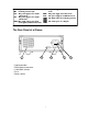
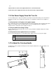
Bench-top viewing positions Carrying position 1.5 To Rack Mount the Instrument You can mount the power supply in a standard 19-inch rack cabinet using the IT-E151 rack mount kit. Note: Remove the carrying handle and the two plastic ears before rack-mounting the instrument. To remove the handle, grasp the handle by sides and pull outwards and rotate it to a special position to let the arrow on the handle and the arrow on the plastic ears be in opposite directions, then pull the handle outward.
To rack mount two instruments side-by-side, order rack mount kit IT-E151, you needn’t to use the front cover panel. unit (mm) Dimension Chapter 2 Specifications 2.1 Specifications Parameter Output Ratings, ( 0 °C - 40 °C) Load Regulation, ±(% of output+offset) Line Regulation, ±(% of output+offset) Programming Resolution Voltage 1785B 0 ~18V 1786B 0 ~32V 1787B 0 ~72V 1788 0 ~32V Current 0 ~5A 0 ~3A 0~1.5V 0~6A LVP 0 ~19V 0 ~33V 0 ~73V 0 ~33V Voltage <0.01% + 3mV Model 1788 = <0.
Programming Voltage <0.05% + 10mV Accuracy, 12months, (@ 25 °C ± 5 °C) ±(% of output+offset) Current <0.2% +10mA Voltage <0.05%+15mV(<20V), <0.05%+120mV(= 20V) Current <0.1% +15mA Voltage 1mVrms/3mVp-p = Current 5mArms Voltage <0.02%+5mV Current <0.1% +5mA Voltage <0.02%+15mV(<20V), <0.02%+120mV(= 20V) Current <0.
Environmental Conditions Designed for indoor use in an installation category II, pollution degree 2 environment. Designed to operate at maximum relative humidity of 95% and at altitudes of up to 2000 meters. Weight Type N.W G.W 1785B 12.3Lbs. 5.6Kg 14Lbs. 6.4Kg 1786B 14.8Lbs. 6.7Kg 16.5Lbs. 7.5Kg 1787B 14.8Lbs. 6.7Kg 16.5Lbs. 7.5Kg 1788 14.8Lbs. 6.7Kg 16.5Lbs. 7.5Kg Dimensions WxHxD* 10” x 4.16” x 15” (255.7mm x 105.7mm x 382.
Chapter 3 Front-panel Operation So far you have learned how to install your power supply and do quick start. During the quick start, you were briefly introduced to operating from the front panel as you learned how to check basic voltage and current functions. This chapter describes in detail the use of the front-panel keys and shows how they are used to accomplish power supply operation.
Step2. Press V-Set key. 0 Step3. Use the numeric keys Step4. Press Enter 9 to or ? and ? keys to change the voltage value. to confirm the value 3.3 Constant Current Operation The constant current output range is from 0A to the maximum current value of each type. It is very easy for you to set the constant current output. Step1. Power on the Power Supply Step2. Press I-Set key 0 to Step3. Use the numeric keys Step4.
Step2. Select >MAX VOLT by using? Step3. Press Enter and ? key. key. Step4. Change the voltage value by using numeric keys Step5. Press Enter 0 to 9 or ? and ? key. key. Note: After you setting the maximum voltage value, the output voltage setup should be in the range from 0 volt to maximum voltage. The default maximum voltage is the full voltage range of its model. n Initiating the Output state(>INIT OUT) This instruction can initiate the output state when the power supply is powered on.
n Setting Address (>ADDRESS) This instruction can set the communication address for each power supply. The address range is from 0 to 254. Before the communication, you must make sure that there is same address between the power supply and the computer. Note: Default address is 0. When the power supply receives a frame instruction from computer, the LINK indicator will light on; it means that the power supply started to communicate with computer.
Chapter 4 Remote Operation Mode The DB9 interface connector on the rear panel of the power supply can be transferred to RS-232 interface, the following information will tell you how to use the computer to control the output of the power supply. 4.
4.3 Frame format Frame length is 26 bytes, the format is as follows: Start Address Command 4-25 bytes are information content Check sum Description: 1. Start bit is AAH, occupies a byte. 2. Address range is 0 to FE, occupies a byte. 3. Command occupies a byte. a. b. c. d. e. f. g. h. i. j. k. l. m. n. o. p. q. r. s. t.
rd Command ( 20H) th Operation mode(0 represent front panel operation mode, 1 represent remote operation mode) System reserve Check sum 3 byte 4 byte th th 5 to 25 byte th 26 byte Note: You can not control the power supply from the front panel when the power supply is in calibration mode. 2.
th 7 byte th th 8 to 25 byte th 26 byte The highest byte of output voltage value System reserve Check sum Note: We use 4 bytes of Hex number to represent an output voltage value. For example the output voltage value is 16.000V and the hex code of 16.000 is th th th th 0X00003EB0, so the 4 byte is 0XB0, 5 byte is 0X3E, 6 byte is 0X00, 7 byte is 0X00. 5.
th To set the low byte of current value th To set the high byte of current value Byte 0 of the maximum voltage value Byte 1 of the maximum voltage value Byte 2 of the maximum voltage value Byte 3 of the maximum voltage value Byte 0 of output voltage value Byte 1 of output voltage value Byte 2 of output voltage value Byte 3 of output voltage value System reserve Check sum 11 byte 12 byte th 13 byte th 14 byte th 15 byte th 16 byte th 17 byte th 18 byte th 19 byte th 20 byte st th 21 to 25 byte th 26 byte
st Start bit(AAH) nd Address(0~0XFE) rd Command(28H) Calibration protection state System reserve Check sum 1 byte 2 byte 3 byte th 4 byte th 5 byte th 26 byte 10. Calibrating the voltage value (29H) st 1 byte nd 2 byte rd 3 byte th 4 byte th th 5 to 25 byte th 26 byte Start bit(AAH) Address(0~0XFE) Command(29H) Calibrated voltage points(point 1-3) System reserve Check sum Note: To calibrate the 3 points of voltage sequentially. 11.
Note: To calibrate the 2 points of the current value sequentially. 13. Sending the actual output current to calibration program (2CH) st 1 byte nd 2 byte rd 3 byte th 4 byte th 5 byte th th 6 to 25 byte th 26 byte Start bit (AAH) Address(0~0XFE) Command(2CH) The lower byte of the present current value The higher byte of the present current value System reserve Check sum 14.
nd 2 byte rd 3 byte th th 4 to 8 byte th 9 byte th 10 byte th th 11 to 20 byte st th 21 to 25 byte Address (0~0XFE) Command( 31H) Product model(ASIC code) Lower byte of the software version Higher byte of the software version Serial number(ASCII code) System reserve th 26 byte Check sum Note: For example, the serial number is 000045, the product model is IT 6811, and software version is V2.
th 26 byte Check sum Note: When the power supply receives a frame command, it will check the frame command, if the check sum is correct, then it will return to 90H, if there is any error on setting parameter or over parameter, then it will return to A0H, if the command wasn’t executed, then it will return to B0H, if the command isn’t effective, then it will return to C0H. Or otherwise, it will return to 80H. Chapter 5 Calibration We suggest you to calibrate the power supply yearly.
5.1 Configuration Start the PC1785B_1788 System, the windows is as follows: The diagram of connecting the multimeter to the calibrated power supply Voltage calibration The diagram of connecting the multimeter to the calibrated power supply Current calibration Before the calibration, please click “Config” button to set the COM interface, address and baud rate. The default Com port is COM, and the default baud rate is 9600.
When you measure the output voltage or short current by the multi-meter, please make sure the value is correct. Otherwise it will cause the calibration failure and let the output turbulence. Please make sure that the maximum current of your multi-meter is higher than the maximum current of the calibrated power supply, otherwise it would damage the multi-meter. 5.
6.3 Functions of PV1785B_1788 Start the software PV1785B_1788, the windows is as follows: 1 2 11 10 3 9 4 5 6 8 7 1 Configure the software operation environments. 2 Voltage chart, it can show you a chart of the voltage. 3 Current chart: it can show you a chart of the current. 4 5 To set the remote mode of power supply. To set the output state ON/OFF.
6.3.1Configure the system The first step for communication is to configure the system, click Configure button windows will display as follows: , the 1) Comm: to set the communication port, baud rate and address. 2) 2) Max voltage: to set a maximum voltage value in the voltage range. For example, the voltage range of IT6822 is 0~32V, then you can set a maximum voltage at 24V. 3) Voltage step: to set the step size of Arrow key, page up/down key, and Mouse-wheel.
6.3.3 Setting Voltage and current 1. Setting voltage/current by rotary knob Use mouse to click on the rotary knob and move mouse to change the value. You also can use mouse wheel, or Page Up/Down keys and arrow keys (?, ?, ? , ? ) from the keyboard to change the voltage value more slightly. The setup value will be displayed on the second line indicator. Use mouse to click on the rotary knob and move mouse to change the value.
3. Program setting Program: Right-click on the Program area, the program tools (Append a line, Insert a line, Delete a line, Delete Select etc.) will appear on the window. Click the tools to program the steps. Double-click on each value to change them from key board as you desired. Also you can change the time unit (hour/minute/second) by clicking on “Sec”. After programming, you can select a run mode for your program. (Run mode includes Once, Repeat and Custom).
6.3.5 Save and Open To save the program settings, quickly settings, voltage sweep settings and GO/NG settings as PAR file. To open the PAR file for reloading the program settings, quickly settings, voltage sweep settings and GO/NG settings. 6.3.6 Present Voltage/Current Chart Double click the voltage chart, the voltage chart will be enlarged and will display as more details. Double click the current chart, the current chart will be enlarged and will display with more details. 6.3.7.
Click here and move to zoom in/out axes or scroll axes To set the ring buffer size To set the limit position To set the Y-Axes Span To set the X-Axes Span Vertical marker Horizontal marker XY Value marker Limit range between the minimum value and maximum value. Scroll axes mode Zoom in/out axes mode Zoom out Zoom in Save the chart as a .BMP file.
Limited One-Year Warranty B&K Precision Corp. warrants to the original purchaser that its product and the component parts thereof, will be free from defects in workmanship and materials for a period of one year from the data of purchase. B&K Precision Corp. will, without charge, repair or replace, at its’ option, defective product or component parts. Returned product must be accompanied by proof of the purchase date in the form a sales receipt. To obtain warranty coverage in the U.S.A.
Service Information Warranty Service: Please return the product in the original packaging with proof of purchase to the below address. Clearly state in writing the performance problem and return any leads, connectors and accessories that you are using with the device. Non-Warranty Service: Return the product in the original packaging to the below address. Clearly state in writing the performance problem and return any leads, connectors and accessories that you are using with the device.
PN: 481-534-9-001 Printed in China 2005 B&K Precision Corp. 22820 Savi Ranch Parkway Yorba Linda, CA 92887 USA TEL: 714-921-9095 FAX: 714-921-6422 38 www.bkprecision.