BK MIKRO LIN.B Tool monitoring system for linear scanning Scanners with maximum stroke of 50 mm or 100 mm Operating Instructions Issue 2.02 dated 31.5.2007 MSC Tuttlingen GmbH Rudolf-Diesel-Straße 17 78532 Tuttlingen Germany Tel. +49 7461 925-276 Fax +49 7461 925-268 E-Mail sales-tut@msc.de www.bk-mikro.
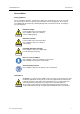
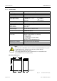
OI: BK MIKRO LIN.B General Notice General Notice Safety guidelines These operating instructions contain notices which you should observe to ensure your own personal safety, as well as to protect the product and connected equipment. These notices are highlighted in the manual by a warning triangle and are marked as follows according to the level of danger: Danger Warning Immediate danger to life and limb of personnel and others. Non-compliance may cause death or serious (crippling) injury.
General Notice OI: BK MIKRO LIN.B Qualification of personnel Only qualified personnel may carry out the following activities on the control system: installation, commissioning, operation, maintenance. Qualified persons in accordance with the safety guidelines are defined as persons who are authorized to commission, to ground, and to tag circuits, equipment, and systems in accordance with established safety practices and standards.
OI: BK MIKRO LIN.B Contents Contents 1 2 2.1 2.1.1 2.1.2 2.1.3 2.1.4 2.1.5 2.1.6 2.2 2.2.1 2.2.2 2.2.3 2.3 3 3.1 3.2 3.3 3.4 3.5 4 4.1 4.1.1 4.1.2 4.1.3 4.2 4.2.1 4.2.2 4.2.3 4.2.4 5 6 6.1 6.2 6.3 7 7.1 7.2 7.3 8 Characteristics ...........................................................................................................................3 System Components .................................................................................................................4 Control unit..........
Table of Figures OI: BK MIKRO LIN.B Table of Figures Fig. 2-1: Fig. 2-2: Fig. 2-3: Fig. 2-4: Fig. 2-5: Fig. 2-6: Fig. 2-7: Fig. 2-8: Fig. 2-9: Fig. 2-10: Fig. 2-11: Fig. 2-12: Fig. 4-1: Fig. 4-2: Fig. 4-3: Fig. 4-4: Fig. 7-1: Fig. 7-2: Fig. 7-3: Control unit – Front view with plug-in connections .................................................................4 Control unit – "Multi" and "Single" ...........................................................................................
OI: BK MIKRO LIN.B 1 Characteristics Characteristics BK MIKRO LIN.B is a tool monitoring system customized for longitudinal scanning applications. The complete BK MIKRO LIN.B system comprises: • a control unit, • a sensor (scanner), • a connection cable. BK MIKRO LIN.B monitors geometries which require longitudinal scanning, especially in cases where rotary scanning is inappropriate or impossible, for example cavities, bore holes, limited space arrangements or critical coolant pressure.
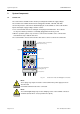
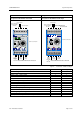
System Components OI: BK MIKRO LIN.B 2 System Components 2.1 Control unit The control unit is available in three models preconfigured for different supply voltages. The relevant version will be marked on the rating plate: 24 VDC, 120 VAC, 230 VAC. On its front panel, the control unit is fitted with plug-in screw terminals to connect all machine inputs and outputs, supply voltage, and the scanner. • The screw terminals have been arranged on two plug-in terminal blocks.
OI: BK MIKRO LIN.B System Components "Multi" "Single" Designation: BK MIKRO LIN.B Multi Designation: BK MIKRO LIN.B Single Control inputs Power supply and Control voltage 24 VDC Control inputs Power supply and Control voltage 24 VDC Selection inputs Com Start Teach S1 S2 + – S3 24 V DC BK MIKRO LIN 25% Scanner 50% 50% Scanner connection 1 2 Home 100 Scanner connection 50 k.o. o.k. k.o. AC IN L1 Scanner 100 0% 50 P2 25% ok: Obj.
System Components 2.1.1 OI: BK MIKRO LIN.B Technical data Housing Insulating material housing, protection class II, built-in unit Protection type IP 20 Dimensions (W x H x D) 45 mm x 75 mm x 107.5 mm Case mountings Sectional rail, 35 mm, to DIN EN 50022 Power supply voltage (depending on model) 24 VDC ±20% PELV1) 120 VAC 230 VAC Power consumption 6 VA max. Control voltage (int./ext.) 24 VDC ±20% PELV1) Inputs - Input current - Pulse duration Galvanically isolated 5 mA approx. 6 ms min.
OI: BK MIKRO LIN.B 2.1.2 System Components Connection terminals Power supply "24 VDC" model: + – + – 24 V DC Supply voltage input 24 VDC Reference potential of 24 VDC supply voltage "120 VAC" and "230 VAC" models 2): AC IN L1 N + – L1 Supply voltage input, depending on model: 120 VAC or 230 VAC N Supply voltage input, depending on model: 120 VAC or 230 VAC + Control voltage for "Start", "Teach" and S1, S2, S3 controlling inputs: 24 VDC unregulated, output current 0.1 A max. If an ext.
System Components OI: BK MIKRO LIN.B Selection inputs Only for "Multi"! S1 S2 S3 S1 S2 S3 The input signal (static) of +24 VDC relative to "Com" terminal must be stable during 50 ms min. before "Teach" or "Start". • "Teach mode" S1, S2, S3 for function "Multi Learn": 3 selection inputs = 8 coded scanning positions A maximum of eight positions can be binary coded via the three selection inputs.
OI: BK MIKRO LIN.B 2.1.3 System Components Light-emitting diodes Three light-emitting diodes (LEDs) on the front panel provide information about the current status of the BK MIKRO LIN.B monitoring system (see chapter "Status Indication"): LED yellow LED red k.o. LED green o.k. AC IN L1 N Fig. 2-4: yellow k.o. o.k. k.o. o.k. Rev. 2.02 dated 31.05.2007 red green red/green Control unit – Light-emitting diodes Power supply / Status Indication of supply voltage and status "K.O.
System Components 2.1.4 OI: BK MIKRO LIN.B Rotary switches Only for "Multi"! The two rotary switches P1 and P2 are used to set the start position and the end position of the range, that is controlled by object monitoring or free space monitoring. P1 0% 75% P2 0% 25% The position settings are possible in steps of 6.25%. 25% The figure shows the setup on delivery. 50% 50% Fig. 2-5: Rotary switches Meaning P1=0, P2=0 Scanning with learn function P1 ≥ 0 P2 > P1 P2 ≤ 93.
OI: BK MIKRO LIN.B 2.1.5 System Components Toggle switches Using the toggle switches, the following functions may be set. "Multi" "Single" Tolerance great Relay N.C. Intensity low Intensity high Intensity high 100 Scanner TK100-LIN.B Relay N.O. Relay N.C. Tolerance great "O.K." at object ok: Obj. 100 Scanner TK100-LIN.B 50 1 Tolerance small 2 Home "O.K." at stop pos. Scanner TK50-LIN.B 50 Scanner TK50-LIN.B Intensity low Tolerance small Fig. 2-6: Relay N.O.
System Components OI: BK MIKRO LIN.B "Tolerance range" switch(es) Range of tolerance for "O.K." message referred to the position learned by "Teach-in": "learned" position Object Range of tolerance Fig. 2-7: "Multi" "Single" 1 ––– 2 1 2 1 ––– 2 1 2 Range of tolerance Tolerance [mm] 0.32 (±0.16) 1 (±0.5) 2 (±1) 10 (±5) "O.K. indication" switch Only for "Multi" ! "O.K." message can be output at different times: Obj. Home 2.1.
OI: BK MIKRO LIN.B 2.2 System Components Scanner The scanner housing is cylindrical and smooth, thus permitting easy installation (e.g. by using a mounting bracket). The scanner is designed for easy access for servicing and changing the wand's tip. Aligning the scanner is easy and requires no additional instruments or aids.
System Components OI: BK MIKRO LIN.B Mechanical dimensions TK50-LIN.B = "50 mm max. stroke" Requirement for correct monitoring: "Scanner" switch at control unit set to "50" ! 17 50 Stop position 49 ø 20 ø4 max. stroke 154 ø 32 73 tip exchangeable, M3x6 Housing Connection cable RO BK RO BK RO BK RO BK 83.5 max. 145 Scanning wand angled connector at the scanner end, 6 pin connector at the control unit end, 6 pin 27.
OI: BK MIKRO LIN.B 2.2.2 System Components Accessories BK MIKRO LIN.B, all scanners ! Scanner tip, brass M3 M3 M3 ø5 ø4 ø4 Scanning tip extension, M3 10 5 65 0.7 x ø2.0 Scanner tip, plastic M3 M3 M3 5 56.5 12 ø6 ø7 ø 4.5 M2.5 ø4 Adapter (with point of fracture in case of damage), M3 12 57 M3 Wand holder ø7 ø 1.3 M2.5 M2.5 21 Fig. 2-10: 2.2.3 Scanners – Accessories Scanning Wand Stop position Stop position Internal backstop approx. 1.
System Components 2.3 OI: BK MIKRO LIN.B Connection cable Control unit and scanner are connected by a 6-wire PUR-cable: • Small circular connector to DIN 45322 at the control unit end. • Molded plug at the scanner end. • Length 5 m, can be extended to a maximum length of approximately 25 m with extension cables.
OI: BK MIKRO LIN.B 3 Mode of Operation Mode of Operation BK MIKRO LIN.B can be operated in different ways: • Monitoring with learn function (Teach mode), especially for "Multi": 8 different scanning positions can be binary coded. • Monitoring with setting scanning range (Switch mode), possible only for "Multi". • Monitoring as object monitoring or free space monitoring, possible only for "Multi". Return travel monitoring is always active. 3.
Mode of Operation 3.3 OI: BK MIKRO LIN.B Output of results • Fault message (K.O.) A fault message will be output immediately on detection. The scanner will return to its stop position. • Good cycle message (O.K.) On reaching the stop position, scanning process results will be indicated. This ensures that the scanner will have left the monitoring range at the time the results are output and that there are no further waiting periods to be considered. Only for "Multi": The indication of "O.K.
OI: BK MIKRO LIN.B Monitoring Functions 4 Monitoring Functions 4.1 Teach mode = Monitoring with learn function "Multi": One of the possible monitoring functions, requirement: P1=0, P2=0 "Single": Standard monitoring function The scanning range will be determined by a learn cycle (external control signal). This mode of operation is the typical mode for tool detection applications: The system will check for the presence of the tool at the learned position. 4.1.
Monitoring Functions 4.1.2 OI: BK MIKRO LIN.B "Start", the real scanning process Active input signal on the "Start" screw terminal of the control unit. The scanner will travel to the previously "learned" position of the object to check for its presence. • If the tool is within the monitoring range, the "O.K." relay will be activated. The tolerance, admissible for a good cycle message (O.K.), can be set by "Tolerance range" switch(es).
OI: BK MIKRO LIN.B 4.2 Monitoring Functions Switch mode = Monitoring with setting the scanning range Only for "Multi"! Requirement: Rotary switches 0 ≤ P1 < P2 ≤ 93.75 Rotary switch P1 and P2 settings will define the scanning range, in steps of 6.25%. P2 Monitoring range vS P1 P1 P2 v1 vmax Object = start position = end position Stop position Fig. 4-3: "Start" cycle using "Switch mode" Captions: vmax = max. speed of scanner v1 = max.
Monitoring Functions 4.2.3 OI: BK MIKRO LIN.B Setting the position The preset position results from the number of pulses which the motor gives to the scanning wand through the gear. Therefore deviations of the device dimensions cause differences of the position. Note: BK MIKRO LIN.B is not an absolute measuring system! Switch setting Position [in mm, approx.] P1, P2 4.2.4 TK50-LIN.B TK100-LIN.B 0 (only P1) 0 0 6.25 3.25 6.5 25 13 26 50 26 52 75 39 78 93.75 (only P2) 48.8 97.
OI: BK MIKRO LIN.B 5 Cycle Times Cycle Times Scanning times The following times designate the moment of the output of results after a scanning process. They result with minimum tolerance. "Teach-in" "Teach-in" "Start" 1) "Start" 1) Intensity low Home O.K. Intensity high Home O.K. Intensity 2) Home O.K. Intensity 2) Obj. O.K.
Status Indication 6 Status Indication 6.1 Yellow LED OI: BK MIKRO LIN.B Fast flashing = Self-test After power-up, the system will carry out a self-test indicated by fast flashing of this yellow LED. Steady illumination = Ready to operate Following its self-test, the system is ready to operate. The LED stops flashing and remains steady. Slow flashing = Scanner fault The system has detected a scanner fault: • Scanner is missing or has motor fault. • Control cable is not correctly connected, e.g.
OI: BK MIKRO LIN.B Installation Notes 7 Installation Notes 7.1 Control voltage connection Power supply GND 24 VDC Power supply and Control voltage Control voltage GND 24 VDC GND 24 VDC Start Teach-in S1 + – 24 V DC Com Start Teach S1 AC IN N L1 K.O. C NO/NC Start Teach-in S1 S2 S3 S2 S3 + – 24 V DC Com Start Teach S1 O.K. C NO/NC AC IN N L1 K.O. C NO/NC BK MIKRO LIN.B 24 VDC common power and control voltage supply S2 S3 S2 S3 O.K. C NO/NC BK MIKRO LIN.
Installation Notes 7.2 OI: BK MIKRO LIN.B Mounting brackets The delivering program offers two mounting brackets for the scanner as accessories. Article no. Designation Material 61 07 082 Mounting bracket [ø 32 mm] AlCuMgPb, F 38, 10 thick, naturally anodized 2 cheese head screws with hexagonal hole M4x60 8.8 zinced 2 self-securing nuts M4 8.8 zinced General tolerances ISO 2768 – mK burred edges Mounting bracket Fig. 7-2: Page 26 of 30 Mounting bracket [ø 32 mm] Rev. 2.02 dated 31.05.
OI: BK MIKRO LIN.B Installation Notes Article no. Designation Material 61 07 165 Mounting bracket [ø 20 mm] AlCuMgPb, F 38, 8 thick, naturally anodized 2 cheese head screws with hexagonal hole M3x40 8.8 zinced 2 self-securing nuts M3 8 zinced General tolerances ISO 2768 – mK burred edges Mounting bracket Fig. 7-3: Rev. 2.02 dated 31.05.
Installation Notes 7.3 OI: BK MIKRO LIN.B Interference prevention All inputs are opto-decoupled and thus maximally protected against interference voltage peaks, as caused, for example, by inductive sources. Relay outputs are protected by varistors against inductive interference voltage peaks. Depending on the type of load used, further interference suppression measures may be necessary. To ensure optimum operational safety, suppression measures, if required, must be taken at source, i.e.
OI: BK MIKRO LIN.B 8 Ordering Information Ordering Information Control unit Article no. BK MIKRO LIN.B Multi 24 VDC 63 04 226 BK MIKRO LIN.B Multi 120 VAC 63 04 227 BK MIKRO LIN.B Multi 230 VAC 63 04 228 BK MIKRO LIN.B Single 24 VDC 63 04 229 BK MIKRO LIN.B Single 120 VAC 63 04 230 BK MIKRO LIN.B Single 230 VAC 63 04 231 Scanner (without cable) Article no. TK50-LIN.B 63 04 224 max. stroke 50 mm TK100-LIN.B max.
Ordering Information Page 30 of 30 OI: BK MIKRO LIN.B Rev. 2.02 dated 31.05.