
Operating instructions


System Components OI: BK MIKRO LIN.B
Page 6 of 30 Rev. 2.02 dated 31.05.2007
2.1.1 Technical data
Housing Insulating material housing, protection class II, built-in unit
Protection type IP 20
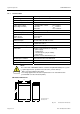
Dimensions (W x H x D) 45 mm x 75 mm x 107.5 mm
Case mountings Sectional rail, 35 mm, to DIN EN 50022
Power supply voltage
(depending on model)
24 VDC ±20% PELV
1)
I
max
= 0.25 A
120 VAC I
max
= 0.05 A
230 VAC I
max
= 0.025 A
Power consumption 6 VA max.
Control voltage (int./ext.) 24 VDC ±20% PELV
1)
Inputs
- Input current
- Pulse duration
Galvanically isolated
5 mA approx.
6 ms min.
Switched outputs 2 x 250 VAC / 30 VDC, 2 A max.
Making/breaking capacity 500 VA / 60 W (max.)
10 mA min. at 10 V
Operational life of relay 5 x 10
7
switching cycles
Connections Plug-in screw terminals for connecting
- power supply
- control inputs
- selection inputs (only for "Multi")
- relay outputs
Scanner socket to DIN 45322, 6 pin
Climatological conditions Classification 3K3 under EN 50178
Ambient temperature 0 ºC to +50 ºC
Storage temperature -25 ºC to +80 ºC
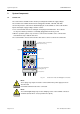
Warning
Note:
The control unit of BK MIKRO LIN.B is a built-in unit (DIN EN 60950)! The system
is explicit approved for operation in closed rooms (control cabinet)!
1)
PELV = Protected Extra Low Voltage
The voltage applied must meet the requirements for an extra low function
potential with safe disconnection (PELV).
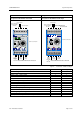
Mechanical dimensions
Fig. 2-3: Control unit – Dimensions
107.5
110
75
78
45
General tolerances
ISO 2768 – mK