
Operating instructions


OI: BK MIKRO LIN.B Contents
Rev. 2.02 dated 31.05.2007 Page 1 of 30
Contents
1 Characteristics ...........................................................................................................................3
2 System Components .................................................................................................................4
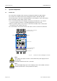
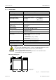
2.1 Control unit...................................................................................................................................4
2.1.1 Technical data..............................................................................................................................6
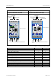
2.1.2 Connection terminals ...................................................................................................................7
2.1.3 Light-emitting diodes....................................................................................................................9
2.1.4 Rotary switches..........................................................................................................................10
2.1.5 Toggle switches .........................................................................................................................11
2.1.6 Notes on technical safety...........................................................................................................12
2.2 Scanner......................................................................................................................................13
2.2.1 Technical data............................................................................................................................13
2.2.2 Accessories................................................................................................................................15
2.2.3 Scanning Wand..........................................................................................................................15
2.3 Connection cable .......................................................................................................................16
3 Mode of Operation ...................................................................................................................17
3.1 Scanning process ......................................................................................................................17
3.2 Reference procedure when system is switched on ...................................................................17
3.3 Output of results.........................................................................................................................18
3.4 Start behavior.............................................................................................................................18
3.5 Return travel monitoring.............................................................................................................18
4 Monitoring Functions ..............................................................................................................19
4.1 Teach mode = Monitoring with learn function............................................................................19
4.1.1 "Teach-in", the learn cycle .........................................................................................................19
4.1.2 "Start", the real scanning process..............................................................................................20
4.1.3 Multi Learn .................................................................................................................................20
4.2 Switch mode = Monitoring with setting the scanning range ......................................................21
4.2.1 Control operation "Object monitoring"........................................................................................21
4.2.2 Control operation "Free space monitoring"................................................................................21
4.2.3 Setting the position.....................................................................................................................22
4.2.4 Example for range settings ........................................................................................................22
5 Cycle Times ..............................................................................................................................23
6 Status Indication ......................................................................................................................24
6.1 Yellow LED.................................................................................................................................24
6.2 Red LED / Green LED ...............................................................................................................24
6.3 Error messages – Flashing red and green LED ........................................................................24
7 Installation Notes .....................................................................................................................25
7.1 Control voltage connection ........................................................................................................25
7.2 Mounting brackets......................................................................................................................26
7.3 Interference prevention..............................................................................................................28
8 Ordering Information ...............................................................................................................29