
Operating instructions

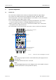
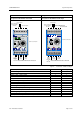

Table of Figures OI: BK MIKRO LIN.B
Page 2 of 30 Rev. 2.02 dated 31.05.2007
Table of Figures
Fig. 2-1: Control unit – Front view with plug-in connections .................................................................4
Fig. 2-2: Control unit – "Multi" and "Single"...........................................................................................5
Fig. 2-3: Control unit – Dimensions.......................................................................................................6
Fig. 2-4: Control unit – Light-emitting diodes ........................................................................................9
Fig. 2-5: Control unit – Rotary switches ..............................................................................................10
Fig. 2-6: Control unit – Toggle switches..............................................................................................11
Fig. 2-7: Range of tolerance................................................................................................................12
Fig. 2-8: Scanner TK50-LIN.B.............................................................................................................14
Fig. 2-9: Scanner TK100-LIN.B...........................................................................................................14
Fig. 2-10: Scanners – Accessories .......................................................................................................15
Fig. 2-11: Stop position of the wand......................................................................................................15
Fig. 2-12: Connection cable – Pin configuration ...................................................................................16
Fig. 4-1: "Teach-in", the learn cycle ....................................................................................................19
Fig. 4-2: "Start" cycle using "Teach mode" .........................................................................................20
Fig. 4-3: "Start" cycle using "Switch mode".........................................................................................21
Fig. 4-4: Range setting using rotary switches .....................................................................................22
Fig. 7-1: Control voltage connection ...................................................................................................25
Fig. 7-2: Mounting bracket [ø 32 mm]......................................................................................................26
Fig. 7-3: Mounting bracket [ø 20 mm]......................................................................................................27
Purpose
These operating instructions are part of the documentation of the BK MIKRO LIN.B.
They provide service personnel and system advisors with the information required
to install, commission, operate and maintain the system BK MIKRO LIN.B.
© Copyright MSC Tuttlingen GmbH, 78532 Tuttlingen, 2007
These operating instructions are available as article no. 68 36 225.
Subject to change without notice.