
Operating instructions


OI: BK MIKRO LIN.B System Components
Rev. 2.02 dated 31.05.2007 Page 5 of 30
"Multi" "Single"
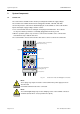
Designation: BK MIKRO LIN.B Multi Designation: BK MIKRO LIN.B Single
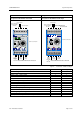
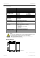
Fig. 2-2: Control unit – "Multi" and "Single"
Features (due to the different control units) "Multi" "Single"
Number of toggle switches 6 4
2 steps for scanning intensity x x
Relay as N.C. or N.O. contact x x
Scanner TK50-LIN.B or TK100-LIN.B x x
Ranges of tolerance for "O.K." (referred to the learned position) 4 2
"O.K." message at "Object" x –
Rotary switches P1, P2 x –
Selection inputs S1, S2, S3 x –
Monitoring of a learned position: Teach mode
x x
Tool monitoring / Object monitoring P1=0, P2=0 Standard
Number of learned positions, that can be stored. 8 1
Monitoring of a preset range: Switch mode
P1 ≥ 0, P2 > 0
–
Object monitoring: "O.K.", if an object is detected. S1=0 –
Free space monitoring: "O.K.", if no object is detected. S1=1 –
Scanner connection
Control inputs
Power supply and
Control voltage
24 VDC
Selection inputs
These terminals must not be connected !
"O.K."
relay
"K.O."
relay
Power
supply
230 VAC
or
120 VAC
Com
24 V DC
Start
Teach
S1
S2
S3
AC IN
L1
N
100
1
2
Home
50
50% 50%
0%
0%
75%
P1
P2
25%
25%
Scanner
k.o.
o.k.
ok: Obj.
BK MIKRO
LIN
Control inputs
Power supply and
Control voltage
24 VDC
These terminals must not be connected!
"O.K."-
Relay
"K.O."-
Relay
Power
supply
230 VAC
or
120 VAC
Scanner connection
These terminals must
be connected!
10050
Scanner
o.k.
L1 N
AC IN
+
–
24 V DC
Com Start Lern
BK MIKRO LINEAR
k.o.